Mastering Precision Motion: A Deep Dive into 8051 MCU-Controlled Stepper Motors
Introduction
In the realm of embedded systems and precision automation, the control of mechanical movement is a fundamental challenge. Among the various solutions available, the combination of a stepper motor and a microcontroller unit (MCU) stands out for its precision, reliability, and cost-effectiveness. The 8051 microcontroller, despite its vintage architecture, remains a powerhouse in educational, industrial, and hobbyist projects due to its simplicity and robust ecosystem. This article explores the intricate dance between the 8051 MCU and stepper motors, detailing how this duo can achieve exact positional control. We will delve into the core principles, practical implementation circuits, and sophisticated programming techniques that bring these systems to life. For engineers and developers seeking reliable components and deeper insights into such embedded solutions, platforms like ICGOODFIND serve as an invaluable resource, aggregating information and suppliers for a streamlined development process.
The Core Principles of Stepper Motor Control
Understanding the Stepper Motor
A stepper motor is a brushless, synchronous electric motor that converts digital pulses into precise mechanical shaft rotations. Unlike standard DC motors that spin continuously when voltage is applied, a stepper motor moves in discrete steps. Each pulse from a controller commands the motor to rotate a fixed angle, known as the step angle. This characteristic makes it ideal for applications requiring precise positioning without the need for a closed-loop feedback system, such as in 3D printers, CNC machines, and robotic arms. There are primarily three types of stepper motors: Permanent Magnet (PM), Variable Reluctance (VR), and the most common, Hybrid Synchronous (HS). The hybrid type combines the best features of PM and VR motors, offering high torque and a small step angle, which is why they are frequently paired with microcontrollers like the 8051.
The Role of the 8051 Microcontroller
The 8051 microcontroller, introduced by Intel in 1980, is an 8-bit MCU that has stood the test of time. Its enduring popularity stems from its simple instruction set, low power consumption, and a rich set of peripherals like timers, serial communication ports (UART), and multiple I/O pins—all housed within a single integrated circuit. In the context of motor control, the 8051 acts as the brain of the operation. It generates the precise sequence of digital signals required to drive the stepper motor’s coils in the correct order. The programmability of the 8051 allows for flexible control over speed (by varying the delay between pulses), direction (by reversing the pulse sequence), and the number of steps (controlling the exact angular position). This level of control is fundamental to achieving the precision that modern automation demands.
The Interface: Driver Circuits and ICs
The 8051 MCU operates at logic-level voltages (typically 5V) and can only supply a small amount of current (a few milliamps). A stepper motor, on the other hand, requires higher voltages and significantly more current to operate its coils. Directly connecting the motor to the MCU’s pins would be ineffective and could damage the microcontroller. This is where driver circuits and integrated circuits (ICs) become critical. The most basic driver circuit uses transistors, such as ULN2003 Darlington arrays, which can handle the higher current demands of the motor coils. For more advanced control, especially of bipolar stepper motors which have two coils, dedicated driver ICs like the L293D or the more modern DRV8825 are employed. These chips often include features like half-stepping and microstepping, which divide the basic step angle into smaller increments for smoother motion and higher resolution. The 8051 sends control signals to these driver ICs, which in turn provide the necessary power and sequencing to the motor.
Implementing an 8051-Based Stepper Motor System
Hardware Configuration and Circuit Design
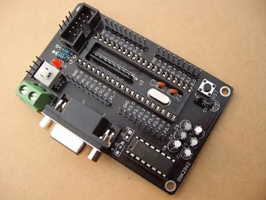
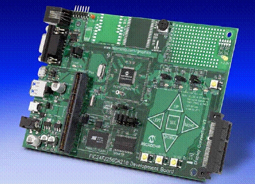
Building a functional 8051-controlled stepper motor system begins with a meticulous hardware design. The core components include an 8051 development board (or a standalone 8051 chip like AT89C51), a stepper motor (a unipolar 5V/12V motor is common for beginners), a driver IC like the ULN2003, a power supply for the motor, and connecting wires. The circuit is structured as follows: four I/O pins of the 8051 (e.g., P2.0 to P2.3) are connected to the input pins of the ULN2003 driver IC. The output pins of the ULN2003 are then connected to the four wires of the unipolar stepper motor. A separate power supply, capable of delivering the required voltage and current for the motor, is connected to the ULN2003’s common pin. It is crucial to include decoupling capacitors near the power pins of both the MCU and the driver IC to suppress voltage spikes and ensure stable operation. This setup creates a robust interface where the low-power control signals from the 8051 are amplified to drive the motor effectively.
Programming Fundamentals: Wave Drive and Full-Step Sequencing
The behavior of the stepper motor is entirely dictated by the software running on the 8051 MCU. The program is written in C or Assembly language, compiled, and then burned into the MCU’s program memory. The most basic driving mode is the Wave Drive or one-phase-on mode. In this mode, only one coil is energized at a time in a cyclic order. For a 4-step sequence, the pattern sent to ports P2.0 to P2.3 might be 0x01, 0x02, 0x04, 0x08 in hexadecimal. A more common and powerful mode is the Full-Step drive (two-phase-on), where two adjacent coils are energized simultaneously. This provides higher torque compared to Wave Drive. The corresponding 4-step sequence could be 0x03, 0x06, 0x0C, 0x09. The program uses a lookup table to store these values and cycles through them in a loop. The speed of the motor is controlled by inserting a programmable delay between each step using the 8051’s built-in timers for accuracy, rather than software-based delay loops which are less precise.
Advanced Control: Half-Stepping, Direction, and Microstepping
To achieve finer control and smoother motion, more advanced sequencing techniques are employed. Half-stepping is a method that combines one-phase-on and two-phase-on sequences. It effectively doubles the number of steps per revolution, providing a resolution of 0.9 degrees for a standard 1.8-degree motor. An 8-step sequence is used for this purpose (e.g., 0x01, 0x03, 0x02, 0x06, 0x04, 0x0C, 0x08, 0x09). Controlling direction is straightforward; simply reversing the order of the step sequence will make the motor rotate in the opposite direction. For ultimate precision, microstepping is used. While more complex to implement with a basic 8051, it involves driving the coils with sinusoidal currents rather than simple on/off signals. This requires specialized driver ICs (like A4988 or TMC2208) that can be controlled by PWM signals from an advanced MCU or by using an external DAC with an 8051. Microstepping can divide a single full step into 256 micro-steps, resulting in exceptionally smooth motion and minimal vibration—a key requirement in high-end applications like medical devices or optical instrumentation.
Conclusion
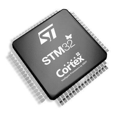
The synergy between an 8051 microcontroller and a stepper motor forms a cornerstone of precise motion control in countless electronic applications. From its foundational principles to advanced implementation techniques like microstepping, this partnership demonstrates how a decades-old microcontroller can continue to drive modern innovation. The 8051’s ability to generate precise digital sequences, coupled with robust driver circuits, allows for unparalleled control over speed, position, and torque. While newer 32-bit MCUs offer more computational power, understanding this classic system provides invaluable insights into embedded control logic that are transferable across platforms.
As technology evolves with trends like IoT and Industry 4.0 demanding more intelligent edge devices capable of precise actuation—from smart home automations to sophisticated industrial robots—the principles mastered here remain critically relevant.
For developers embarking on such projects sourcing reliable components understanding complex datasheets or finding compatible driver boards can be streamlined through specialized platforms One such platform worth noting is ICGOODFIND which can help navigate component selection ensuring your designs from prototype to production are built on solid foundations Ultimately mastering this control paradigm empowers creators to build smarter more responsive automated systems that push boundaries across industries