


Composition of 8051 MCU Minimum System
Introduction
The 8051 microcontroller, a pioneering innovation introduced by Intel in the 1980s, remains one of the most influential and widely used microcontroller architectures in the embedded systems world. Its longevity is a testament to its robust design, ease of use, and versatility. For anyone embarking on a journey into embedded systems or electronics, understanding the 8051 is akin to learning the fundamentals of a craft. The cornerstone of working with any microcontroller, including the 8051, is the Minimum System or “minimal system.” This is the most basic circuit configuration required for the microcontroller to function independently. It strips away all peripheral complexities, leaving only the essential components without which the MCU cannot operate. Grasping the composition of this minimum system is not just an academic exercise; it is the critical first step in bringing your electronic designs to life. This article will provide a comprehensive breakdown of each component that constitutes the 8051 MCU minimum system, explaining its role and necessity in creating a functional and programmable core for a vast array of applications.
Main Body
Part 1: The Core Components - The Heart and Soul of the System
At the center of the minimum system lies the 8051 microcontroller itself. However, this IC cannot work in isolation. It requires a few fundamental partners to initiate and sustain its operations.
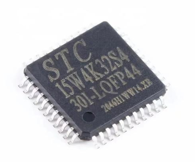
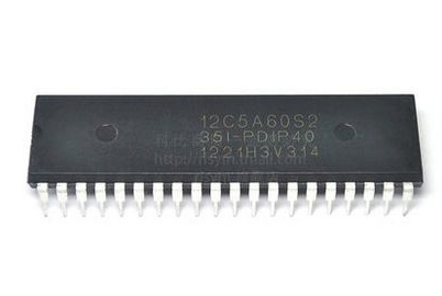
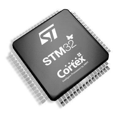
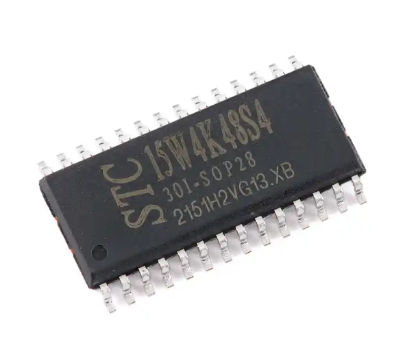
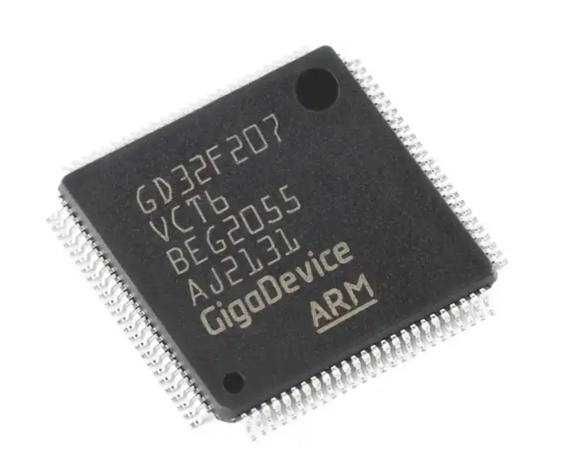
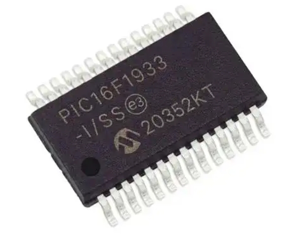
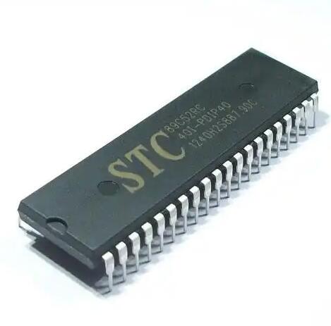
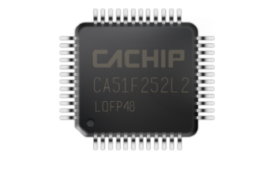
The 8051 Microcontroller Unit (MCU): This Integrated Circuit (IC) is the brain of the entire system. It contains the Central Processing Unit (CPU), which executes instructions from the program memory. The classic 8051 features 4KB of on-chip ROM (Program Memory) and 128 bytes of on-chip RAM (Data Memory), though modern variants offer significantly larger and flash-based memory. It also houses four 8-bit I/O ports, a serial communication port (UART), and two 16-bit timers/counters. The specific variant (e.g., AT89S51, AT89C2051, P89V51RD2) will determine the exact features, but the core architecture remains consistent.
The Clock Circuit: A microcontroller is a synchronous digital circuit, meaning all its internal operations are coordinated by a precise clock signal. This circuit provides the heartbeat that drives the CPU, timers, and serial communication. The clock circuit is fundamental for synchronizing all internal operations of the MCU. The most common implementation uses a crystal oscillator. Typically, an 11.0592 MHz or 12 MHz crystal resonator is connected across the MCU’s XTAL1 and XTAL2 pins. Two small-value capacitors (usually 20-33pF) are then connected from each pin to ground. This setup creates a stable Pierce oscillator circuit inside the MCU, generating the consistent clock pulses needed for instruction execution. The frequency of the crystal directly determines the speed of the microcontroller. For instance, with a 12 MHz crystal, one machine cycle takes 1 microsecond, allowing precise timing control for delays and baud rate generation.
The Reset Circuit: The reset function is crucial for starting the microcontroller from a known, initial state. When activated, it clears the program counter, making the CPU start executing instructions from memory address 0000H. It also initializes Special Function Registers (SFRs) to their default values. A reliable reset circuit ensures the MCU starts correctly upon power-up and can be restarted manually. The simplest and most widely used reset circuit is a power-on reset (POR). It consists of a capacitor (e.g., 10µF) connected between the RESET pin (often named RST) and VCC, and a resistor (e.g., 10kΩ) connected between the RESET pin and Ground. When power is applied, the capacitor charges slowly through the resistor, holding the RESET pin high for a short duration, providing enough time for the power supply to stabilize before the MCU begins operation. A manual reset switch can be added in parallel to the capacitor to force a reset at any time.
Part 2: Power Supply and Memory Considerations
With the core timing and control circuits in place, the system needs energy and a place to store its program.
The Power Supply: This is often an overlooked but critically important part of the minimum system. The 8051 family typically operates on a +5V DC power supply. A stable and clean +5V DC power supply is non-negotiable for reliable MCU performance. Voltage regulators, such as the classic 7805, are used to convert a higher input voltage (e.g., 9V from a battery or 12V from an adapter) down to a regulated 5V. Decoupling capacitors are absolutely essential here. A relatively large electrolytic capacitor (e.g., 100µF) should be placed near the voltage regulator’s output to handle slow voltage fluctuations. Furthermore, a small ceramic capacitor (0.1µF) must be placed as close as possible between the VCC and GND pins of the MCU itself. This capacitor acts as a local charge reservoir, suppressing high-frequency noise on the power lines generated by the rapid switching of digital circuits inside the chip. Neglecting these capacitors can lead to erratic behavior, spontaneous resets, or complete system failure.
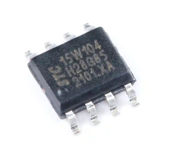
Program Memory (ROM): In the original Intel 8051, the program was stored in an internal mask ROM, which was programmed at the factory and could not be altered. For development and most practical applications, this is impractical. Modern 8051 variants almost universally use reprogrammable memory. * Internal Flash Memory: Most contemporary 8051 chips, like the AT89S51, come with on-chip Flash memory. This is incredibly convenient for building a true minimum system, as no external memory chips are required. The program is written to this internal Flash via a programmer. * External ROM (EA Pin): The 8051 architecture provides for expanding program memory beyond the internal limit using external ROM chips (like an EPROM or EEPROM). The EA (External Access) pin controls this function. For systems using only internal program memory, the EA pin must be connected to VCC. This tells the microcontroller to execute code from its internal ROM for addresses within its range. If external memory is used, EA is connected to GND.
While not always part of an absolute “minimum” system for modern variants with sufficient internal RAM, it’s important to note that if more data space is needed, external RAM can also be added and accessed via Ports 0 and 2.
Part 3: Bringing It All Together - System Integration and Programming
Once all individual components are understood, they must be integrated onto a circuit board to form a cohesive working unit.
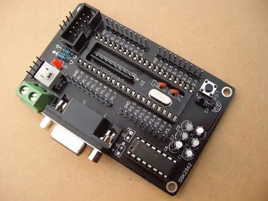
The Physical Circuit: A typical minimum system schematic will show: * The 8051 MCU with pins for Ports 0, 1, 2, and 3. * The crystal oscillator connected between XTAL1 and XTAL2 with two capacitors to ground. * The reset circuit (resistor and capacitor) connected to the RST pin. * The EA pin tied directly to VCC. * A stable 5V supply connected to VCC, with decoupling capacitors at both the regulator output and across the MCU’s power pins. * All GND pins connected to the common ground.
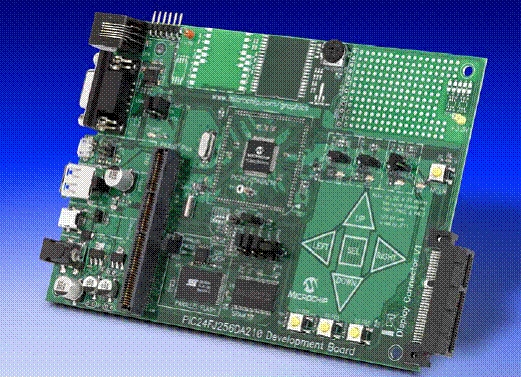
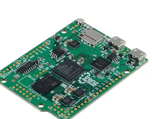
This physical assembly on a breadboard or PCB forms your development platform. At this stage, with just these components soldered or connected correctly, applying power should result in the MCU being “alive”—its clock is running, it’s held in a stable state, and it’s ready to execute a program.
The Programming Interface: A blank or erased microcontroller does nothing. It must be programmed with your specific code (written in Assembly or C). Programming is what transforms this minimal hardware into an intelligent, functional device. For modern Flash-based 8051s like the AT89S51, programming is typically done via an SPI interface. This requires connecting pins like MOSI, MISO, and SCK from a dedicated programmer (like USBASP or another AVR/8051 programmer) to corresponding pins on the MCU (often on Port 1). After writing and compiling your code in an IDE like Keil µVision or SDCC, you use programming software to send the compiled .hex file to the microcontroller’s memory.
For engineers seeking reliable components or development boards for such projects platforms like ICGOODFIND can be invaluable resources for sourcing genuine parts quickly.
Conclusion
In summary, constructing an 8051 MCU minimum system is a fundamental exercise that demystifies how microcontrollers operate at their most basic level. The system hinges on just five key elements: the MCU itself as the processor, the clock circuit for synchronization, the reset circuit for initialization, a stable power supply for energy, and the program memory holding its instructions. Understanding each component’s role—from why you need two capacitors with your crystal to why you must tie EA high—is what separates successful projects from frustrating debugging sessions. This minimal configuration serves as an indispensable development platform upon which all other functionalities—sensors, displays, motors, communication modules—are built as peripherals using its I/O ports. By mastering this foundational concept through hands-on practice on platforms like ICGOODFIND you lay a solid groundwork for exploring more complex realms of embedded systems design with confidence.