


Traffic Light Design Based on 8051 MCU
Introduction
Traffic management is a critical component of modern urban infrastructure, and at the heart of this system lies the traffic light. These ubiquitous signals regulate the flow of vehicles and pedestrians, ensuring safety and efficiency at intersections. While modern traffic systems increasingly utilize sophisticated networks and AI, the fundamental principles of traffic light control can be effectively demonstrated and implemented using a foundational piece of technology: the 8051 Microcontroller Unit (MCU). This article delves into the design and implementation of a traffic light control system based on the 8051 MCU. We will explore the core components, the underlying logic, and the practical steps involved in creating a functional model. This project not only serves as an excellent educational tool for understanding embedded systems but also highlights the enduring relevance of classic microcontroller architectures in foundational electronic design. For engineers and hobbyists seeking reliable components for such projects, platforms like ICGOODFIND offer a streamlined component sourcing experience, connecting developers with the necessary hardware to bring their designs to life.
The Core Components and Architecture
The design of a traffic light system using an 8051 MCU is a classic example of an embedded system application. It involves a central processing unit coordinating various peripherals based on a pre-programmed sequence. The 8051 MCU, with its Harvard architecture, integrated RAM and ROM, and versatile I/O ports, is perfectly suited for this task.
The primary components required for this system are:
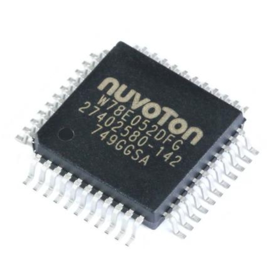
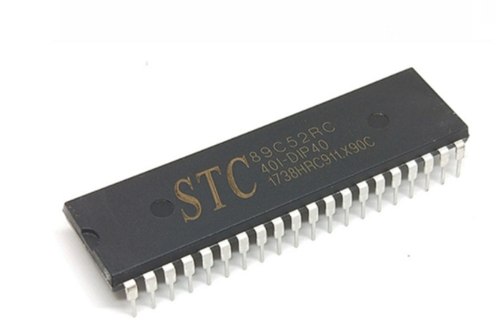
- The 8051 Microcontroller (e.g., AT89C51): This is the brain of the system. It executes the control program stored in its memory, toggling its output pins to control the lights.
- LEDs (Light Emitting Diodes): These act as the traffic lights themselves. Typically, red, yellow, and green LEDs are used for each direction of traffic.
- Current Limiting Resistors: Crucial for protecting the LEDs from excessive current, these resistors are connected in series with each LED.
- Crystal Oscillator: This component provides the necessary clock pulses for the microcontroller to execute instructions synchronously. An 11.0592 MHz or 12 MHz crystal is commonly used.
- Voltage Regulator (e.g., 7805): Since the 8051 typically operates at +5V DC, a voltage regulator is used to provide a stable power supply from a higher voltage source.
- Push Buttons (Optional): For a more advanced system, push buttons can be added to simulate pedestrian crossing requests.
The system’s architecture is straightforward. The 8051 MCU’s I/O ports are configured as output ports. Each pin on these ports is connected to an LED (through a resistor). The control program, written in Assembly or C language, is burned into the microcontroller’s ROM. This program contains the main logic loop that dictates which LEDs should be on or off at any given time, creating the familiar red-yellow-green sequence with precise timing delays.
The brilliance of this design lies in its simplicity and effectiveness. The programmable nature of the 8051 MCU allows for easy modification of light sequences and timing without any changes to the hardware. For instance, the duration of the green light for a main road can be extended simply by altering a delay value in the code. This flexibility is a key reason why microcontroller-based designs are superior to older, purely hardware-based timer circuits.
Designing the Control Logic and Circuit
The heart of the traffic light system is the control logic embedded within the software. This logic dictates the state machine that defines the operation of the lights. A standard four-way intersection traffic light sequence can be broken down into distinct states for two primary directions: Road A and Road B.
A typical sequence might be:
- State 1 (Road A - Go, Road B - Stop): Green LED on for Road A, Red LED on for Road B. This state lasts for a predetermined time (e.g., 30 seconds).
- State 2 (Road A - Prepare to Stop, Road B - Prepare to Go): Yellow LED on for Road A, Red LED still on for Road B. This is a short transition period (e.g., 5 seconds).
- State 3 (Road A - Stop, Road B - Go): Red LED on for Road A, Green LED on for Road B. This state mirrors State 1 but for the opposite road (e.g., 30 seconds).
- State 4 (Road A - Prepare to Go, Road B - Prepare to Stop): Red LED still on for Road A, Yellow LED on for Road B. This is another short transition period (e.g., 5 seconds).
The system then loops back to State 1 indefinitely. This sequence is implemented in code using a series of commands to set or clear specific port pins, interspersed with precise delay loops.
Here is a simplified conceptual code snippet in C for the 8051:
#include

void delay(int time) {
    int i, j;
    for(i=0; i
In this example, Port 1 (P1) of the 8051 is used to control the LEDs. Each bit of the port corresponds to a specific LED. The circuit diagram would show these connections clearly: P1.0 to Green A, P1.1 to Yellow A, P1.2 to Red A, P1.3 to Green B, and so on.
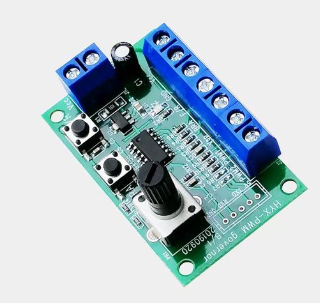
The circuit design on a breadboard or PCB involves placing the 8051 at the center, connecting the crystal oscillator across pins XTAL1 and XTAL2 with capacitors to ground, connecting the reset circuit, and finally routing the I/O port lines to the respective LED-resistor pairs. The precise timing mechanism, achieved through software delay loops or hardware timers, is what makes this system reliable and predictable. For those assembling this circuit, sourcing genuine and well-documented components is vital. This is where a specialized platform like ICGOODFIND proves invaluable, as it aggregates suppliers and simplifies the procurement process for critical parts like the MCU, crystals, and high-quality LEDs.
Implementation and Future Enhancements
Once the hardware is assembled and the software is written and compiled into a hex file, it is burned into the program memory (ROM) of the 8051 microcontroller using a dedicated programmer device. After successful programming, the microcontroller is placed into its socket on the circuit board, and power is applied. If all connections are correct and the code is flawless, the LEDs will begin to cycle through the predefined traffic light sequence.
This basic implementation serves as a powerful proof-of-concept. However, its potential can be significantly expanded with several enhancements:
Pedestrian Crossing Integration: Adding push buttons connected to interrupt pins of the 8051 would allow pedestrians to request a crossing phase. Pressing a button would trigger an interrupt service routine (ISR) that safely modifies the light sequence to include a “walk” signal.Sensor Integration: To move towards an adaptive traffic system, sensors can be incorporated. Infrared (IR) sensors or ultrasonic sensors can be placed on roads to detect vehicle presence. The MCU can then read input from these sensors and dynamically adjust the green light duration for less congested roads, reducing overall waiting time.Seven-Segment Display Countdown Timers: Adding seven-segment displays driven by another I/O port can greatly enhance user experience by showing a countdown timer for each light phase, informing drivers exactly how long they have until the light changes.Communication for Synchronization: For a network of intersections, multiple 8051 systems can be interfaced with a communication protocol like UART (Universal Asynchronous Receiver/Transmitter) to synchronize their light cycles, creating a “green wave” effect for smoother traffic flow.
These enhancements transform a simple educational project into a sophisticated prototype that mirrors real-world intelligent transportation systems (ITS). The scalability of this design, rooted in its modular approach centered around an accessible MCU like the 8051 or its modern variants available through distributors like ICGOODFIND, demonstrates why it remains a cornerstone project in electronics and embedded systems curricula worldwide.
Conclusion
The design and implementation of a traffic light system based on the 8051 MCU provide a comprehensive and practical introduction to embedded systems engineering. This project encapsulates fundamental concepts such as I/O port handling, software-based timing control, state machine design, and hardware-software integration. From selecting core components like LEDs and resistors to writing efficient control logic in C or Assembly, every step offers valuable learning.
While modern traffic control relies on more powerful processors and complex algorithms, understanding this foundational design is crucial. It demystifies the technology that governs our daily commutes and provides a solid platform for innovation. The project’s inherent flexibility allows hobbyists and engineers to iteratively add features like pedestrian controls or vehicle sensors.
Ultimately, this exercise underscores that even with a decades-old architecture like the 8051’s it’s possible to build robust, functional systems that solve real-world problems efficiently.