8051 MCU Running Lights: A Comprehensive Guide to Embedded LED Control
Introduction
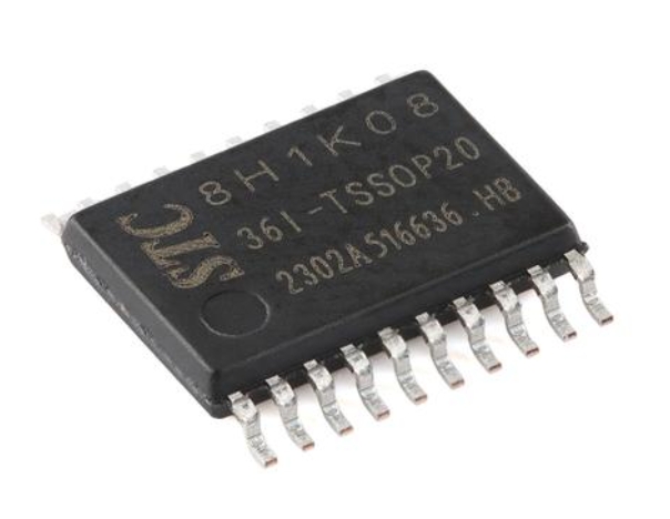
The 8051 microcontroller has stood the test of time as one of the most influential and widely-used embedded systems in electronics history. Originally developed by Intel in 1980, this 8-bit MCU architecture continues to power countless applications across industries, from simple consumer electronics to sophisticated industrial automation systems. Among the most fundamental and educational projects for understanding embedded systems is creating running lights - a sequential LED pattern that demonstrates core concepts of microcontroller programming and hardware interfacing. This project serves as an excellent entry point for both beginners and experienced engineers looking to refresh their skills with this timeless architecture. The simplicity of the 8051’s design combined with its powerful instruction set makes it ideal for learning embedded concepts that translate to more modern microcontroller families. Through this comprehensive guide, we’ll explore not just how to create basic running light patterns, but how to optimize them for real-world applications while understanding the underlying principles that make the 8051 such an enduring platform in the embedded world.
The Architecture of 8051 Microcontroller
Core Components and Memory Organization
The 8051 microcontroller features a Harvard architecture with separate memory spaces for program and data, which enables simultaneous access and improved performance for embedded applications. At its heart lies an 8-bit CPU operating at clock frequencies typically ranging from 12MHz to 24MHz in modern variants, though original implementations ran at just 12MHz. The memory architecture includes 4KB of ROM (or Flash in contemporary versions) for program storage and 128 bytes of RAM for data manipulation, with some derivatives expanding these capacities significantly. Special Function Registers (SFRs) play a crucial role in controlling the microcontroller’s peripherals and I/O ports, providing dedicated addresses for hardware configuration and status monitoring.
One of the most distinctive features of the 8051 architecture is its bit-addressable memory space, which allows individual bits to be set or cleared without affecting other bits in the same byte. This capability proves particularly valuable for LED control applications like running lights, where precise manipulation of individual output pins is required. The four 8-bit I/O ports (P0, P1, P2, and P3) provide 32 general-purpose digital I/O lines, though some ports serve dual functions for external memory interfacing or communication peripherals. Understanding this architecture is fundamental to writing efficient code for running lights, as it enables developers to leverage the microcontroller’s built-in capabilities rather than implementing software workarounds.
Timers and Interrupt System
The 8051 incorporates two or three 16-bit timers/counters (depending on the variant) that are essential for creating precise timing in running light applications. These hardware timers can generate accurate delays without consuming CPU cycles in busy-wait loops, enabling the microcontroller to perform other tasks while maintaining precise timing for LED patterns. The timer modes include simple interval timing, event counting, and baud rate generation for serial communication, with Timer 0 and Timer 1 being standard across all 8051 derivatives.
The interrupt system represents another critical aspect of the 8051 architecture, featuring five interrupt sources with two priority levels. For running light implementations, timer interrupts provide the most efficient method for creating consistent pattern timing while allowing the main program to handle other responsibilities. The interrupt vector table located at specific memory addresses ensures that when an interrupt occurs, the processor immediately jumps to the corresponding service routine. This hardware-managed context switching preserves program state automatically, simplifying development compared to software-based polling approaches. Mastering these architectural elements transforms simple running light projects into professional-grade embedded applications.
Implementing Running Lights with 8051
Basic Circuit Design and Hardware Configuration
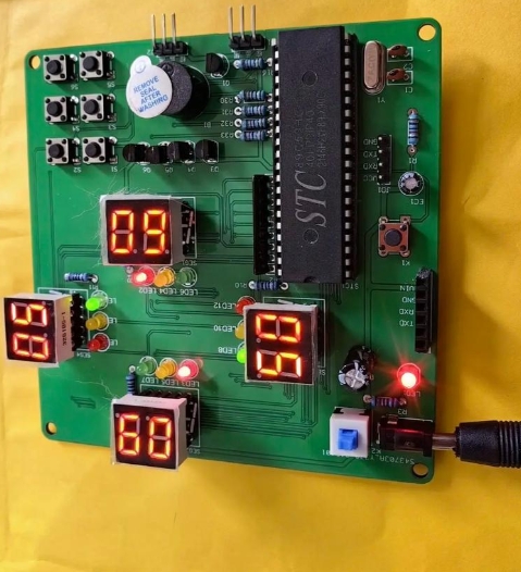
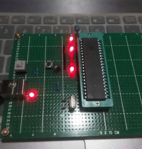
Creating running lights with an 8051 begins with proper circuit design that ensures both functionality and component protection. The fundamental configuration involves connecting LEDs to one of the microcontroller’s I/O ports, typically through current-limiting resistors to prevent damage to both the LEDs and the microcontroller pins. A common approach uses Port 1 or Port 2 since these ports have internal pull-up resistors in many 8051 variants, simplifying circuit design. Each LED should be connected with its anode to the microcontroller pin and cathode to ground through a resistor, or alternatively in a common-cathode configuration depending on the desired current sourcing or sinking approach.
The value of the current-limiting resistor is critical and calculated based on the forward voltage of the LEDs and the desired current, typically between 10-20mA for standard brightness. Using Ohm’s Law (R = (Vcc - Vf) / I), where Vcc is the supply voltage (usually 5V for traditional 8051), Vf is the LED forward voltage (approximately 2V for red LEDs), and I is the desired current, we arrive at resistor values around 220-330 ohms. For more advanced running light displays, multiplexing techniques allow controlling a larger number of LEDs with fewer I/O pins by rapidly switching between groups of LEDs. This approach requires additional transistors for current amplification and careful timing in software to maintain consistent brightness across all elements. Proper decoupling capacitors placed near the power pins of the microcontroller ensure stable operation by filtering power supply noise that could cause erratic behavior in the running light patterns.
Programming Fundamentals and Delay Generation
The software implementation of running lights revolves around manipulating port registers to turn LEDs on and off in sequence while introducing controlled delays between state changes. The most straightforward approach uses simple shift operations combined with delay loops to create the running effect. In Assembly language, this involves loading a pattern value into the accumulator, outputting it to a port, then rotating left or right before repeating after a delay. The delay subroutine typically consists of nested loops that consume a specific number of clock cycles, with the exact values calculated based on the crystal frequency and desired delay duration.
For more efficient and responsive implementations, developers utilize the 8051’s hardware timers instead of software delay loops. This method involves configuring one of the timers to generate interrupts at regular intervals, with the interrupt service routine (ISR) handling the LED pattern advancement. The key steps include initializing the timer in mode 1 (16-bit timer mode), calculating reload values for the desired interval, enabling timer interrupts, and writing the ISR that modifies the port output. This approach allows the main program to perform other tasks while maintaining precise timing for the running lights. Additionally, using lookup tables stored in code memory enables complex patterns that go beyond simple shifting, such as bouncing effects, random patterns, or mathematical sequences that would be computationally intensive to generate in real-time.
Advanced Techniques and Optimization Strategies
Pattern Complexity and Memory Efficiency
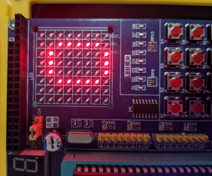
As running light projects evolve from simple demonstrations to sophisticated displays, implementing complex patterns efficiently becomes paramount. Beyond basic left/right shifting, advanced sequences might include knight rider scanner effects, binary counters, circular patterns, or mathematically-generated designs like Fibonacci sequences. Each pattern type presents unique implementation challenges regarding code size execution speed and timing accuracy. For memory-constrained applications developers can employ algorithmic pattern generation that calculates LED states mathematically rather than storing extensive pattern tables in ROM significantly reducing memory usage while maintaining pattern complexity.
Another crucial optimization involves balancing pattern variety against resource limitations particularly in production systems where cost reduction is essential. Code compression techniques such as storing only pattern differences between frames or using run-length encoding for repetitive sequences can dramatically reduce memory requirements. Additionally intelligent initialization routines that configure multiple hardware parameters with single instructions minimize setup code while ensuring reliable operation. When working with extensive LED arrays developers must consider refresh rates and visual persistence principles to maintain apparent continuous illumination while minimizing processor load through efficient scanning algorithms.
Hardware Enhancements and Real-World Applications
While basic running lights can be implemented with minimal components professional applications often incorporate hardware enhancements to improve performance or functionality. External shift registers like the 74HC595 enable controlling numerous LEDs with just three microcontroller pins significantly expanding display capabilities without requiring more expensive microcontrollers with higher pin counts. For high-power LEDs or large arrays driver transistors or dedicated LED driver ICs provide necessary current capacity while protecting the microcontroller from excessive loads.
In industrial contexts running lights transcend decorative purposes serving as status indicators in control panels fault detection systems or operational sequence displays. Automotive applications include turn signal indicators warning light sequences and entertainment system displays. Consumer electronics utilize similar patterns for audio visualizers power status indicators or user interface elements. The principles learned from basic 8051 running lights directly translate to these real-world applications where reliability efficiency and precise timing are critical. Platforms like ICGOOEFIND provide valuable resources components and community support for developers advancing from simple prototypes to commercial products leveraging the versatile 8051 platform.
Conclusion
The implementation of running lights using the 8051 microcontroller demonstrates fundamental embedded systems concepts that remain relevant despite decades of technological advancement. Through this exploration we’ve seen how the 8051’s architecture particularly its bit-addressable ports hardware timers and interrupt system provides an ideal foundation for both learning and practical applications. The progression from simple delay-based implementations to interrupt-driven designs using hardware timers mirrors the development path of embedded engineers moving from basic concepts to optimized professional solutions.
The enduring popularity of the 8051 for educational purposes stems from its transparent architecture that clearly exposes how software interacts with hardware—a quality sometimes obscured in more modern complex microcontrollers. Furthermore platforms like ICGOOEFIND continue to support this timeless architecture with development tools component sources and community knowledge ensuring new generations of engineers can benefit from hands-on experience with this foundational technology. As we’ve discovered the humble running light project encapsulates principles that scale from blinking a single LED to controlling sophisticated display systems proving that mastery of fundamentals remains the surest path to embedded systems expertise regardless of how microcontroller technology evolves.