8051 MCU Applications: From Scratch
Introduction
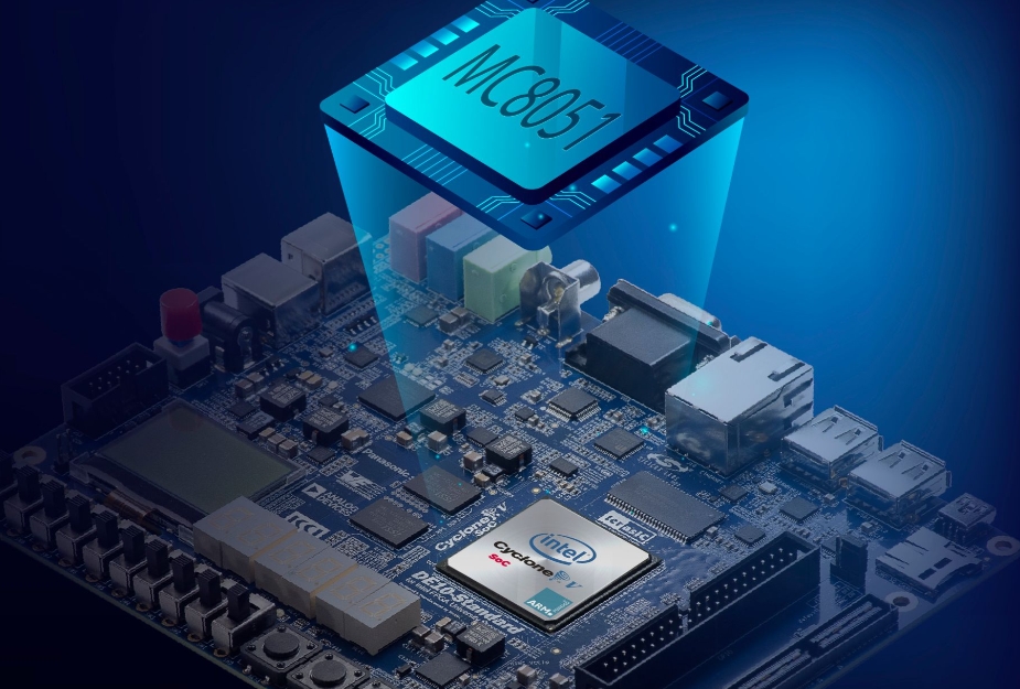
The 8051 microcontroller, introduced by Intel in the 1980s, remains one of the most influential and widely used microcontroller architectures in the embedded systems world. Despite the advent of more modern and powerful microcontrollers, the 8051 continues to thrive due to its simplicity, robustness, and extensive ecosystem. For engineers, students, and hobbyists embarking on embedded systems projects, understanding how to build 8051 MCU applications from scratch provides a foundational skill set that is transferable to many other platforms. This journey from concept to functional implementation demystifies the hardware-software interaction that is central to embedded design. This article serves as a comprehensive guide for developing applications with the 8051 microcontroller, starting with the absolute basics. We will explore its core architecture, walk through the initial setup and toolchain, and demonstrate practical application development. Throughout this process, platforms like ICGOODFIND can be invaluable resources for sourcing components, finding datasheets, and connecting with a community of developers.

Part 1: Understanding the 8051 Microcontroller Architecture
Before writing a single line of code, it is crucial to understand the hardware you are programming. The 8051’s enduring popularity stems from its well-organized and relatively simple internal architecture, which provides a clear model for how a microcontroller operates.
The Core Building Blocks of the 8051
At its heart, the 8051 is an 8-bit microcontroller, meaning it processes data in 8-bit chunks. Its architecture consists of several key components that work in harmony:
- Central Processing Unit (CPU): This is the brain of the microcontroller. It fetches instructions from memory, decodes them, and executes them. The 8051’s CPU includes an Arithmetic Logic Unit (ALU) for performing mathematical and logical operations.
- Memory Organization: The 8051 has a Harvard architecture, which means it has separate memory spaces for program code and data.
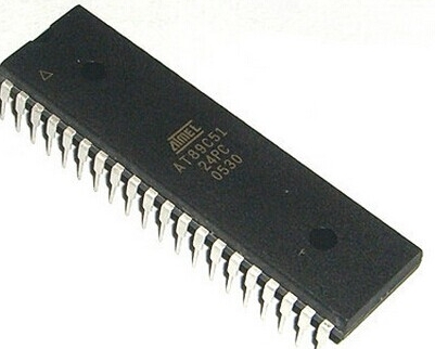
- Program Memory (ROM): This is where the final application code is stored. In original versions, this was a mask ROM, but modern variants use Flash memory (e.g., AT89S51) or One-Time Programmable (OTP) ROM, allowing for easier reprogramming.
- Data Memory (RAM): This is volatile memory used for temporary data storage during program execution. The 8051 has a limited internal RAM of 128 bytes (often expanded in newer variants), which is divided into register banks, bit-addressable space, and general-purpose scratchpad memory.
- Special Function Registers (SFRs): These are a critical set of registers mapped into the RAM space that control the various peripherals of the microcontroller. By reading from and writing to these registers, the programmer can configure timers, serial communication, and I/O ports. Key SFRs include
ACC(the accumulator),B,PSW(Program Status Word),SP(Stack Pointer), andDPTR(Data Pointer). - Input/Output (I/O) Ports: The 8051 typically features four 8-bit I/O ports (P0, P1, P2, and P3). These pins are the physical interface between the microcontroller and the outside world. They can be configured as inputs to read sensor data or as outputs to control LEDs, motors, and displays.
- Timers/Counters: Two or three 16-bit timers/counters (Timer 0, Timer 1, and sometimes Timer 2) are available. They are incredibly versatile and can be used for generating precise delays, creating baud rates for serial communication, or counting external events.
- Serial Communication Interface (UART): The built-in UART allows the 8051 to communicate serially with other devices like a PC, GPS module, or another microcontroller. This is essential for data logging and debugging.
Understanding this architecture is the first step in mastering 8051 MCU applications from scratch. It allows you to visualize how your code interacts with the hardware to perform real-world tasks.
Part 2: Setting Up Your Development Environment
With a theoretical understanding in place, the next step is to set up a practical development environment. This involves selecting hardware, installing necessary software tools, and writing your first simple program.
Essential Hardware and Software Tools
To start developing for the 8051, you will need:
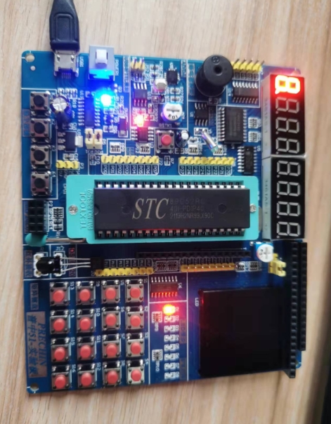
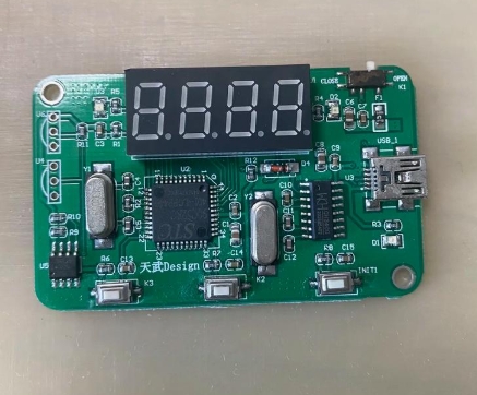
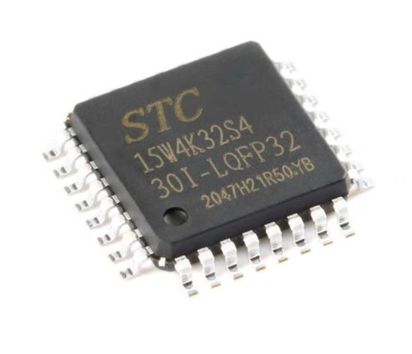
- An 8051 Development Board or Kit: A beginner-friendly board often includes the microcontroller, a crystal oscillator, reset circuitry, LEDs, and sometimes a USB programmer. For those sourcing components or looking for specific board models, ICGOODFIND offers a platform to search for and compare different kits and individual parts.
- A Programmer/Debugger: This hardware device is used to transfer your compiled code from the PC to the microcontroller’s program memory. Common programmers include USBasp (with an adapter) or dedicated 8051 programmers like the ones from Silicon Labs.
- Software Toolchain:
- An Integrated Development Environment (IDE): Keil µVision is a very popular and powerful IDE for 8051 development. It includes a project manager, a sophisticated editor, and integrated debugger support. Alternatives like SDCC (Small Device C Compiler) with a simpler editor like VS Code are also available.
- A Compiler/Assembler: This translates the human-readable code (C or Assembly) into machine code (hex file) that the microcontroller can execute. The Keil IDE bundles its own C compiler.
- Flash Utility: This is the software that interfaces with your programmer hardware to “burn” the hex file onto the MCU.
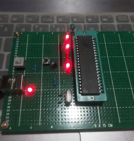
Writing and Flashing Your First Program: “Blinky”
The “Hello World” of embedded systems is making an LED blink. This simple task validates your entire toolchain.
-
Create a New Project: In your IDE (e.g., Keil µVision), create a new project targeting your specific 8051 variant (e.g., AT89S52).
-
Write the Code: Create a new C file (
main.c) and write the following code. This program toggles an LED connected to pin P1.0.#include // Include the SFR definitions for the 8051 void delay(void) { // A simple software delay function int i, j; for(i=0; i<1000; i++) for(j=0; j<100; j++); } void main(void) { // The main function, where program execution starts while(1) { // Infinite loop P1_0 = 0; // Set P1.0 low (turn LED on if connected with cathode to ground) delay(); // Call delay function P1_0 = 1; // Set P1.0 high (turn LED off) delay(); // Call delay function } } -
Build the Project: Compile the code to generate a HEX file. If there are no errors, the build process will be successful.
-
Flash the Microcontroller: Use your flash utility and programmer hardware to load the generated HEX file onto the 8051.
-
Test: Power up or reset your board. You should see the LED blinking steadily.
This process of writing, building, flashing, and testing is the fundamental workflow for creating any 8051 MCU application from scratch.
Part 3: Developing Practical Applications from Scratch
Once you have mastered blinking an LED, you can progress to more complex and practical applications. This involves leveraging other built-in peripherals of the 8051.
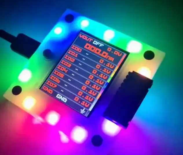
Interfacing with Displays and Sensors
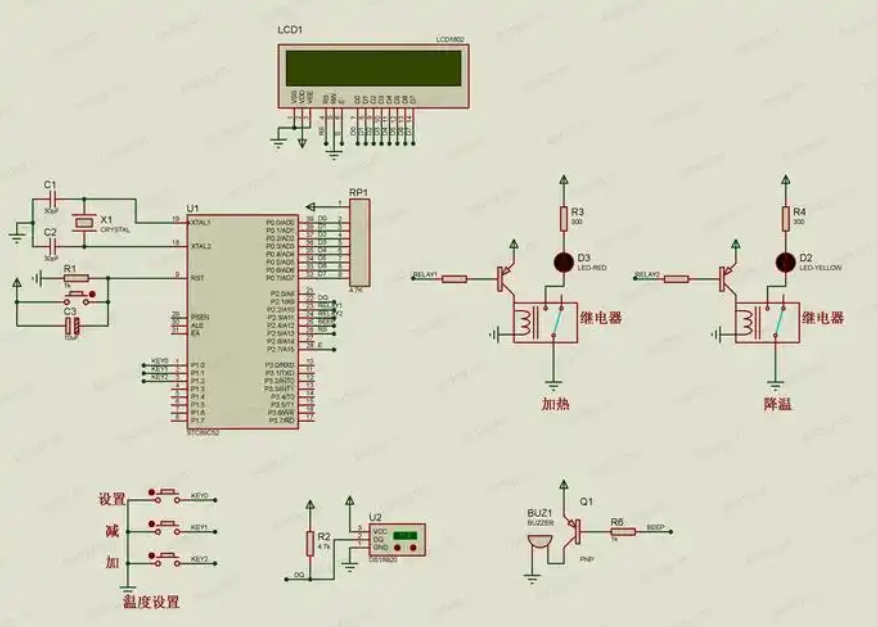
A common requirement is to display information. Interfacing with a 16x2 LCD character display is a classic project.
- Concept: The LCD is controlled by sending commands and data through its parallel interface, which is typically connected to one of the 8051’s ports.
- Implementation: You would write functions to initialize the LCD, send commands (like “clear screen”), and send data (the characters you want to display). This involves carefully toggling the control pins (RS, R/W, E) according to the LCD’s datasheet timing diagrams.
Similarly, you can interface with sensors like: * Temperature Sensor (e.g., LM35): This analog sensor requires connecting to an ADC (Analog-to-Digital Converter). Since most basic 8051s lack an internal ADC, you would need an external ADC chip like ADC0804, which communicates with the 8051 via its I/O ports. * Digital Sensors: Modern sensors often communicate via digital protocols like I2C or SPI. While not natively supported by the original 8051 core, these protocols can be implemented in software by “bit-banging” – manually controlling I/O pins to generate the required signal waveforms.
Utilizing Timers and Interrupts for Efficient Control
The delay() function used in the blinky example is inefficient because it wastes CPU cycles in a loop. For precise timing and responsive systems, you must use timers and interrupts.
- Timers: Instead of a software loop, you configure one of the hardware timers to overflow at a precise interval (e.g., every 50ms). This is done by calculating and loading a value into the timer’s registers.
- Interrupts: You then enable the timer overflow interrupt. When the timer overflows, it signals the CPU, which temporarily pauses the main program execution and jumps to a special function called an Interrupt Service Routine (ISR). Inside the ISR, you can toggle the LED and reload the timer.
- Benefits: This method is far more efficient. The CPU is free to execute other code in the
main()loop while waiting for the timer interrupt. This allows your application to perform multiple tasks seemingly simultaneously.
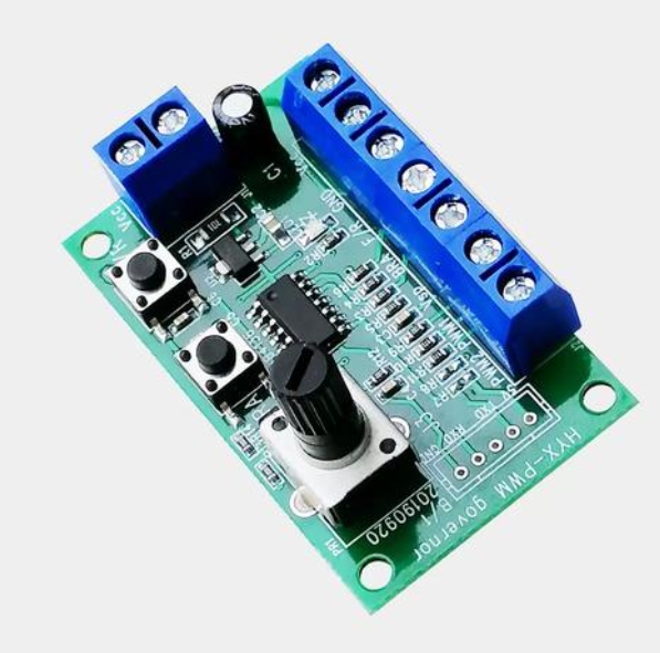
Mastering timers and interrupts is a significant milestone in moving from simple scripts to robust 8051 MCU applications from scratch. It unlocks capabilities like generating precise Pulse-Width Modulation (PWM) for motor speed control or reading encoder inputs without missing counts.
Conclusion
The journey of creating 8051 MCU applications from scratch is a deeply rewarding endeavor that builds a solid foundation in embedded systems engineering. Starting with a fundamental understanding of its architecture empowers you to make informed decisions. Setting up a functional development environment bridges theory and practice. Finally, progressing from simple I/O control to leveraging sophisticated peripherals like timers and interrupts enables you to build efficient and responsive real-world systems. While newer architectures exist, principles learned on this platform—direct register manipulation ISR management—are universally applicable across all microcontrollers today whether ARM RISC V etc For developers seeking components datasheets or inspiration platforms such as ICGOODFIND serve as excellent hubs accelerating development process by providing necessary resources community support Ultimately proficiency gained through hands on experience with remains invaluable asset for any aspiring embedded systems engineer.