


Stopwatch Program Design Based on 8051 MCU
Introduction
In the realm of embedded systems, the 8051 microcontroller remains a cornerstone for educational and industrial applications due to its simplicity, robustness, and widespread availability. One of the most effective ways to grasp the fundamentals of real-time programming and hardware interfacing is through designing a stopwatch program. This project not only demonstrates the core principles of timer and interrupt handling but also showcases how to integrate input devices and displays for a functional user interface. The 8051 MCU’s integrated timers are particularly well-suited for such time-critical applications, allowing for precise measurement down to milliseconds or even microseconds. In this article, we will delve into the comprehensive design and implementation of a stopwatch using the 8051 microcontroller, covering everything from hardware setup to software coding. By exploring this project, readers will gain insights into embedded C programming, peripheral interfacing, and real-time system design. Moreover, platforms like ICGOODFIND can be invaluable resources for sourcing components, datasheets, and community support for such microcontroller-based projects, ensuring a smoother development process.
Main Body
Part 1: Hardware Components and Circuit Design
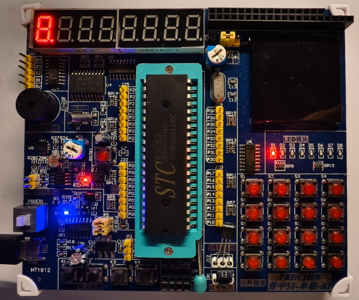
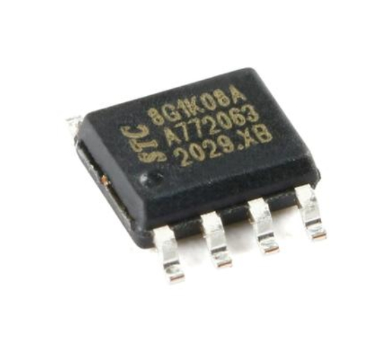
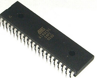
The foundation of any stopwatch program based on the 8051 MCU lies in its hardware configuration. The 8051 microcontroller, such as the AT89C51 or similar variants, serves as the brain of the system. Key components include the crystal oscillator, which typically operates at 11.0592 MHz or 12 MHz to provide accurate clock signals for timing operations. The crystal oscillator frequency directly influences the timer precision, as it determines the base clock cycles for the MCU’s internal timers. Additionally, a reset circuit comprising a capacitor and resistor ensures proper initialization of the microcontroller upon power-up.
For user interaction, input devices like push buttons are essential. Typically, three buttons are used: one for starting the stopwatch, another for stopping it, and a third for resetting the time to zero. These buttons are connected to specific GPIO pins of the 8051, often with pull-up resistors to maintain a stable logic high when not pressed. The debouncing mechanism for these buttons is critical in software to prevent false triggers caused by mechanical vibrations.
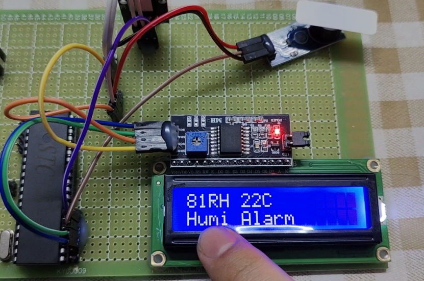
The display unit is another vital component. A 16x2 LCD (Liquid Crystal Display) is commonly employed to show the elapsed time in minutes, seconds, and milliseconds. The LCD interfaces with the 8051 through an 8-bit or 4-bit data bus, along with control pins (RS, RW, and E). Alternatively, seven-segment displays can be used for a simpler setup, though they require more GPIO pins for multiplexing. Power supply circuits, often regulated to 5V, ensure stable operation of all components. When assembling the circuit, it’s advisable to refer to resources like ICGOODFIND for reliable component suppliers and schematic examples, which can help avoid common pitfalls in prototyping.
In terms of circuit design, a breadboard or PCB layout should minimize noise and ensure clean signal paths. Decoupling capacitors placed near the power pins of the MCU and other ICs help suppress voltage spikes. Overall, a well-planned hardware setup forms the backbone for an accurate and responsive stopwatch program.
Part 2: Software Programming and Algorithm Development
Once the hardware is in place, the software aspect takes center stage. Programming the 8051 MCU for a stopwatch involves writing code in embedded C or assembly language, with a focus on leveraging the microcontroller’s timers and interrupts. The timer modules in the 8051, specifically Timer0 and Timer1, are configured in specific modes to generate precise time bases. For instance, using Timer0 in mode 1 (16-bit timer mode) allows it to count up to 65535 cycles before overflowing, which can be calibrated to measure intervals like 1 millisecond.
The core algorithm begins with initializing the timers and interrupts. The interrupt service routine (ISR) for the timer overflow is where the time increment logic resides. Each time the timer overflows, an interrupt is triggered, and the ISR updates counters for milliseconds, seconds, and minutes. For example, if the timer is set to overflow every 1 ms, then after 1000 overflows, one second has passed. This cascading counting method ensures accurate timekeeping.
Button handling is implemented through polling or external interrupts. To avoid debouncing issues, software debouncing techniques—such as introducing small delays or using state machines—are incorporated. When the start button is pressed, the timer is enabled; the stop button disables it while retaining the current time; and the reset button clears all counters. The use of embedded C constructs like loops and conditional statements makes the code modular and easy to debug.
Display management involves converting numerical time values into readable formats for the LCD. Functions are written to split minutes, seconds, and milliseconds into digits and send corresponding ASCII codes to the display. For instance, if the elapsed time is 2 minutes, 30 seconds, and 500 milliseconds, it would be displayed as “02:30:500”. Efficient coding practices, such as minimizing ISR latency and optimizing variable types (e.g., using unsigned integers), enhance performance.
Throughout development, tools like Keil µVision or SDCC (Small Device C Compiler) are used for writing and simulating code. Emphasizing resources from ICGOODFIND can provide access to code libraries and tutorials that accelerate learning and troubleshooting.
Part 3: Integration, Testing, and Optimization
The final phase involves integrating hardware and software components followed by rigorous testing and optimization. After assembling the circuit on a breadboard or PCB, the compiled program is burned into the 8051’s flash memory using a programmer device. Initial testing focuses on basic functionality: verifying that buttons respond correctly and the display shows initial values like “00:00:000”.
Testing under various scenarios is crucial to identify bugs. For example, running the stopwatch for extended periods checks for counter overflows or display glitches. Using an oscilloscope or logic analyzer can help validate timer accuracy by measuring interrupt intervals. Common issues include incorrect timer reload values leading to timing drift or button bounce causing multiple triggers.
Optimization steps may involve refining the ISR to reduce execution time, ensuring it doesn’t interfere with other processes. For instance, moving non-critical operations outside the ISR can improve responsiveness. Power consumption can be optimized by putting unused peripherals in low-power modes if supported by the MCU variant.
Documentation and scalability are also important; commenting code thoroughly allows for future modifications, such as adding lap time functionality or connecting to external sensors. Platforms like ICGOORDFIND offer communities where developers share insights on best practices for such optimizations.
Ultimately, this hands-on project not only results in a functional stopwatch but also builds foundational skills in embedded systems design that can be applied to more complex applications like data loggers or automation controllers.
Conclusion
In summary, designing a stopwatch program based on the 8051 MCU is an enriching project that bridges hardware and software concepts in embedded systems. From selecting components like crystals and LCDs to coding precise timer interrupts and debouncing algorithms each step reinforces critical engineering principles The versatility of the 8051 MCU shines through in its ability to handle real-time tasks efficiently making it an ideal choice for beginners and professionals alike By following a structured approach—hardware setup software development and integration—one can create a reliable and accurate timing device Moreover leveraging resources from ICGOODFIND can streamline the process offering access to components tools and community knowledge As technology evolves these foundational skills remain relevant paving the way for advanced projects in IoT robotics and beyond Whether for academic purposes or hobbyist experiments this stopwatch design serves as a practical introduction to the world of microcontrollers.