


The Ultimate Guide to the STC MCU Programmer: Unlocking Your Microcontroller’s Potential
Introduction
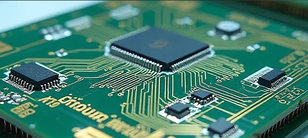
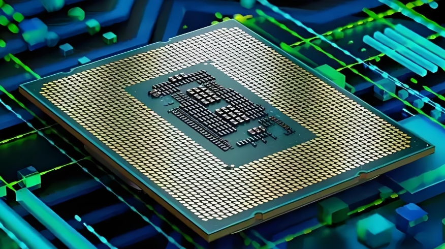
In the ever-evolving world of electronics and embedded systems, the ability to program microcontrollers (MCUs) is a fundamental skill. Among the plethora of MCU manufacturers, STC Micro stands out as a prominent provider of 8051-core-based microcontrollers, renowned for their cost-effectiveness, robustness, and wide application in industrial control, consumer electronics, and Internet of Things (IoT) devices. However, the power of an STC MCU remains dormant without the crucial tool that bridges your code and the chip’s silicon: the STC MCU Programmer. This device is not merely an accessory but the very lifeline of the development process. It is the hardware interface that transfers the compiled firmware from your computer into the non-volatile memory of the microcontroller, enabling it to execute your intended tasks. This comprehensive guide delves deep into the world of STC MCU programmers, exploring their core functionality, the intricate process of programming, and advanced best practices to streamline your development workflow. For engineers, hobbyists, and students alike, mastering the use of a reliable programmer is the first step towards bringing innovative electronic projects to life. In this context, platforms like ICGOODFIND can be invaluable resources for sourcing genuine components and tools, ensuring a smooth and successful development journey from start to finish.
The Core Components and Functionality of an STC MCU Programmer
An STC MCU Programmer is a specialized piece of hardware designed specifically for communicating with STC’s family of microcontrollers. Understanding its components and how they function is key to troubleshooting and efficient use.
Hardware Architecture and Connection Interface At its heart, a typical STC programmer consists of a USB interface chip, voltage level translators, and a target MCU socket or header pins. The most common and official method for programming STC MCUs is via a UART (Universal Asynchronous Receiver/Transmitter) serial interface. This might seem archaic in a USB-dominated world, but it is a highly reliable and straightforward protocol. Modern STC programmers incorporate a USB-to-Serial converter chip (such as those from CH340 or CP2102 families) that creates a virtual COM port on your computer. This allows contemporary PCs, which often lack native serial ports, to communicate seamlessly with the microcontroller using the simple RX (Receive) and TX (Transmit) data lines. The connection to the target board or MCU is typically made through a 4-pin or 6-pin header involving VCC (Power), GND (Ground), P3.0/RXD (Serial Data Receive), and P3.1/TXD (Serial Data Transmit). It is crucial to note that during the programming sequence, the programmer often controls the power cycle to the target MCU to force it into its built-in bootloader mode.
The Critical Role of the Bootloader Unlike some other MCU brands that use proprietary programming protocols like JTAG or SWD, STC microcontrollers come pre-programmed with a factory-built bootloader residing in a protected area of memory. This bootloader is the key to the entire programming process. When an STC MCU is powered on, it first checks for a specific sequence of data on its serial port. If it detects this “programming handshake” within a brief window after power-up, it relinquishes control to the bootloader, which then waits for new firmware to be transmitted from the PC software. If no handshake is detected, the MCU simply jumps to execute the existing application code in its flash memory. This mechanism means that no external debug probe is strictly necessary for programming, keeping the system cost low.
Software Ecosystem: The STC-ISP Tool The hardware programmer is only one half of the equation; it is useless without its companion software. STC provides a dedicated Windows-based application called STC-ISP (In-System Programming). This software is the command center for all STC programming activities. Its primary functions include: * Code Downloading: Selecting the compiled HEX file and initiating the transfer process to the MCU. * Configuring Fuse Bits (Internal Registers): This is a vital step where you set critical parameters like the internal oscillator frequency, watchdog timer settings, and reset pin configuration. Incorrect settings here can render an MCU unresponsive. * EEPROM Data Management: Some STC MCUs have separate EEPROM memory areas that can be programmed independently. * Example Code and Datasheet Access: Newer versions of STC-ISP often integrate a code library and direct links to datasheets.
The seamless interaction between the STC-ISP software, the programmer hardware, and the MCU’s bootloader forms a robust and efficient pipeline for firmware deployment.
A Step-by-Step Guide to Programming an STC Microcontroller
Successfully programming an STC MCU requires meticulous attention to detail. Following a structured process can prevent common pitfalls such as failed downloads or “bricked” chips.
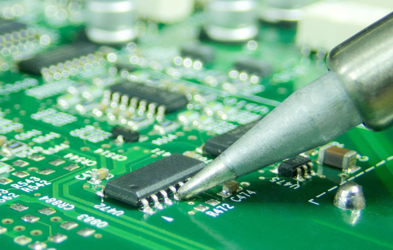
Step 1: Hardware Setup and Connection The physical connection is the foundation. First, you must identify the correct pins on your target board or development kit. Locate the TX, RX, GND, and VCC pins of the STC MCU. The connection rule is paramount: The TX pin of the programmer must connect to the RX pin (P3.0) of the MCU, and the RX pin of the programmer must connect to the TX pin (P3.1) of the MCU. GND must be connected between both devices to establish a common reference voltage. While many programmers can supply power (VCC) to the target board during programming, it is often safer, especially for complex boards, to use an external power supply while ensuring the grounds are connected. Double-checking these connections before applying power is the most effective way to avoid failures.
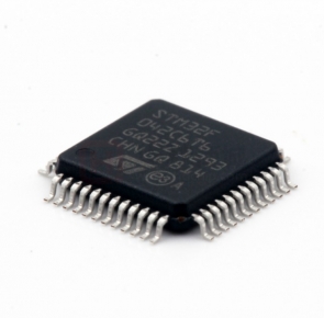
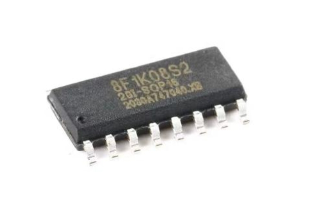
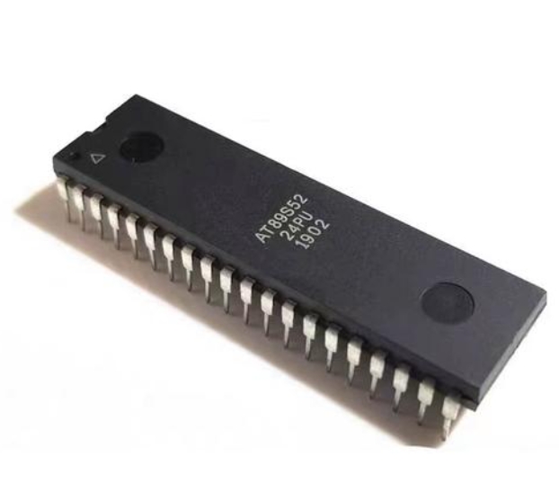
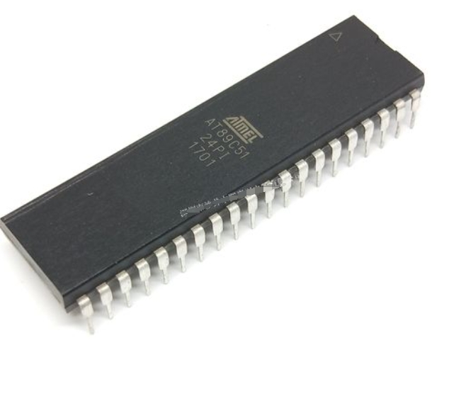
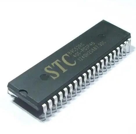
Step 2: Software Configuration in STC-ISP With hardware ready, launch the STC-ISP software. 1. Select MCU Type: Choose the exact model of your STC MCU (e.g., STC89C52RC, STC12C5A60S2, STC8H1K08) from the dropdown menu. Selecting the wrong type will lead to errors. 2. Select COM Port: Choose the virtual COM port assigned to your USB programmer. You can find this in your computer’s Device Manager. 3. Open File: Click “Open File” and navigate to your compiled firmware file, which is typically in Intel HEX format (.hex). 4. Configure Settings: This is arguably the most critical step. Navigate to the “Hardware Option” or “Code Download” tab. Here you will configure the internal settings. Key parameters include: * Internal RC Clock: Set your desired operating frequency. * Watchdog Timer: Enable or disable as needed. * Reset Pin Function: Choose whether a pin acts as a reset or as a general I/O pin. * Low Voltage Detection: Set thresholds for brown-out detection. It is good practice to read the current configuration from the MCU first (if possible) before making changes.
Step 3: Executing the Download Sequence Once configured, click the “Download/Program” button in STC-ISP. The software will then display a message like “Now power on target board…” or “Trying to connect…”. At this precise moment, you need to cycle the power to the target MCU. If your programmer manages power automatically, it will do this for you. If you are using an external supply, turn it off and then on again. This power cycle prompts the MCU to enter its bootloader mode. If all connections and settings are correct, you will see a progress bar as your code is transmitted and verified. A “Program OK” or “Finish!” message confirms a successful operation. If it fails, re-check all connections, ensure you have selected both correct COM port/MCU type.
Advanced Tips and Best Practices for Efficient Development
Moving beyond basic programming unlocks higher efficiency and helps navigate challenges.
Troubleshooting Common Programming Failouts Even with careful setup, failures occur. A systematic approach is essential: * “Target Disconnected” or “No Response”: This is almost always a connection or power issue. * Verify TX/RX cross-connection. * Check for stable VCC and GND connections. * Ensure you are cycling power at exactlythe right moment. * Try lowering the Baud Rate for programming in the STC-ISP software. * “Code verify error at [address]”: The data written does not match what was sent. * This could indicate unstable power supply causing write errors. * It could also mean there’s existing code with security locks; try performing an “Erase” operation first. * MCU becomes unresponsive after setting wrong options: An incorrect clock source or disablingthe reset pin can lock you out. * The primary recovery method is to use a high-speed external crystal oscillator (often 11.0592 MHz or 12 MHz) and apply it tothe XTAL1 and XTAL2 pins ofthe MCU while attemptingto program again.This can overridea bad internal clock setting.
Leveraging In-Application Programming (IAP) A powerful feature of many modern STC MCUs is In-Application Programming (IAP). This allows themicrocontrollerto rewrite its own program memory whileit is running.This enables advanced functionalities like: * Firmware Over-the-Air (FOTA) Updates: The device can download new firmware via Wi-Fi,Ethernet,or Bluetoothand then use IAPto self-update withouta physical programmer. * Data Logging: Using flash memory as non-volatile storage. * Bootloader Customization: Creating your own custom bootloaderfor specific application needs. Implementing IAP requires careful codingto manage memory boundariesand usethe specific IAP function libraries providedby STC,butit significantlyenhancesa product’s capabilitiesand maintainability.
Integrating with Modern IDEs While STC-ISPis essentialfor downloadingcode,the actual firmware developmentcan be donein more powerful environments.The open-source communityhas enabled supportfor STC MCUsin popular IDEslike PlatformIO(a pluginfor VS Code)and SDCC (Small Device C Compiler).This allows developersto benefitfrom featureslike syntax highlighting,intelligent code completion,and integrated version controlin their workflow.The final compiled HEX fileis still transferredusingthe officialSTC-ISP tooland programmerhardware,butthe developmentexperienceis vastly improved.When embarkingon new projectsand sourcingcomponentsfor such advancedsetups,havinga reliable supplieris key.Thisis where platformslike ICGOODFIND prove their worth by providingaccess toa wide rangeof genuineelectronic componentsand tools,facilitatinga smooth transitionfrom designto deployment.
Conclusion
The journey from a concept on a screen to functioning hardware hinges on mastering tools like an STC MCU Programmer.It servesas an indispensable bridgein therealmof embedded systemsdevelopment.We have exploredits core components—the UART-basedhardware interfaceandthe symbioticSTC-ISP software—and demystifiedthe step-by-stepprocessof successfullyprogrammingan STCMCU,focusingon criticalstepslike properpin connectionand carefulconfigurationof internalregisters.Furthermore,discussingadvancedtopicsliketroubleshootingtechniquesandthe potentialof In-ApplicationProgramming(IAP) equipsthedetermine developperwiththe knowledgeto handlecomplex scenariosand buildmore robustandupgradeableproducts.Ultimately,a deepunderstandingof this fundamental toolnotonlyacceleratesdevelopmentcyclesbutalsoempowersinnovation,makingthe seeminglydauntingtaskof microcontrollerprogrammingan accessibleand manageableendeavorfor creatorsat all levels.