


The Ultimate Guide to MCU Programmer/Burner: Tools, Techniques, and Best Practices
Introduction
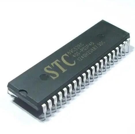
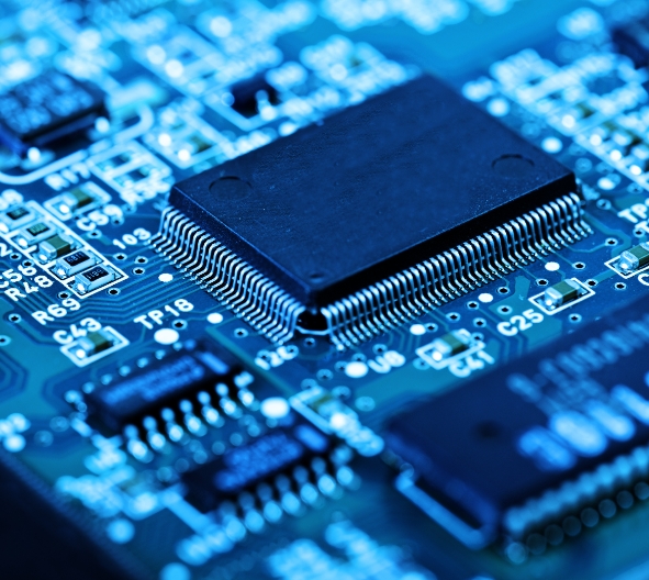
In the rapidly evolving world of embedded systems and electronics development, the MCU Programmer/Burner stands as a critical bridge between software code and physical hardware. Whether you’re a hobbyist prototyping a new idea or an engineer mass-producing devices, understanding and utilizing the right programming tools is fundamental. An MCU (Microcontroller Unit) programmer, often called a burner, is a hardware device that transfers compiled machine code from a development environment into the non-volatile memory (like Flash or EEPROM) of a microcontroller. This process, known as “burning” or “programming,” breathes life into silicon, transforming it from an inert chip into a functional component of a smart system. This comprehensive guide delves into the core aspects of MCU programmers, exploring their types, key functionalities, and the pivotal role they play in modern electronics workflows.

Main Body
Part 1: Understanding MCU Programmers/Burners and Their Core Functionality
At its heart, an MCU Programmer/Burner is a communication intermediary. It translates commands from a host computer (running specialized software) into precise electrical signals that the target microcontroller can understand and accept for storing program data.
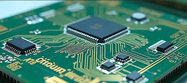
The programming process typically follows a standard sequence. First, the developer writes source code in languages like C or C++, which is then compiled or assembled into a binary file (often .hex or .bin). This file contains the raw machine instructions. The programmer hardware is connected to the host PC via USB, Ethernet, or older interfaces like parallel ports. On the target side, it connects to the MCU through specific pins dedicated to programming, such as SWD (Serial Wire Debug), JTAG, ISP (In-System Programming), or ICSP (In-Circuit Serial Programming) interfaces. The programmer’s software then controls the process of erasing old memory, writing new data, and verifying the integrity of the written code.
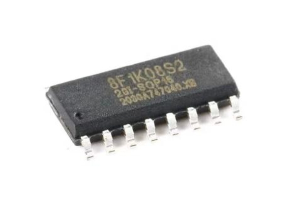
Several critical protocols and standards govern this communication. JTAG (Joint Test Action Group) is a venerable standard used not only for programming but also for boundary-scan testing. SWD (Serial Wire Debug), popularized by ARM Cortex cores, offers a faster two-wire alternative. ISP (In-System Programming) allows the MCU to be programmed after it’s soldered onto a PCB, which is invaluable for field updates and production. The choice of protocol depends heavily on the MCU architecture and the manufacturer’s specifications.
Part 2: Types of MCU Programmers and How to Choose the Right One
The market offers a diverse range of programmers, each suited for different stages of development and production.
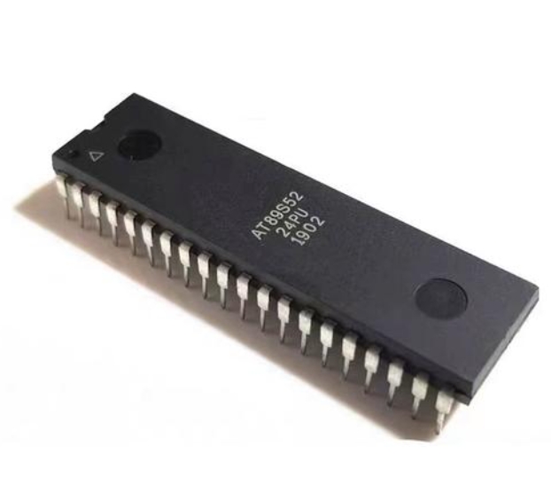
- Development/Debug Programmers: These are the workhorses for engineers and hobbyists. Devices like ST-LINK (for STM32), J-Link (from SEGGER), and Atmel-ICE (for AVR and SAM MCUs) are prime examples. They combine programming functionality with advanced debugging features like real-time breakpoints, memory inspection, and single-stepping code. Their primary value lies in the iterative development cycle, allowing developers to quickly test and modify code.
- Gang/Production Programmers: Speed and reliability are paramount in manufacturing. A gang programmer can program multiple MCUs simultaneously before they are placed on circuit boards. Standalone devices that can operate without a connected PC are also common on production lines. These tools prioritize throughput, robustness, and support for tape-and-reel components to streamline mass production.
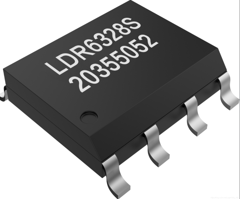
- Universal Programmers: As the name suggests, these devices aim to support a vast array of chip types—not just MCUs but also memory chips (EEPROM, Flash), PLDs, and more. They achieve this through adaptable pin drivers and constantly updated software libraries. While sometimes slower than dedicated tools, they offer exceptional flexibility for labs or repair centers handling many different components.
- Bootloader-Based Programming: This is a software method rather than dedicated hardware. A small bootloader program resides permanently in the MCU’s memory. It allows the main application firmware to be updated via simple serial interfaces like UART, USB, or CAN. This method is crucial for enabling Firmware-Over-The-Air (FOTA) updates in connected devices.
Choosing the right programmer involves evaluating several factors: compatibility with your target MCU family (both current and future), required programming speed for your volume needs, essential features like debugging support, budget constraints, and the reliability of the vendor’s software/driver support.
Part 3: Best Practices for Successful and Efficient MCU Programming
Mastering the use of an MCU Programmer/Burner involves more than just connecting cables; it requires adherence to proven practices.
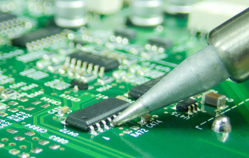
- Connection Integrity is Paramount: A poor physical connection is the leading cause of programming failures. Always double-check pin alignment on adapters and sockets. Use high-quality cables and ensure target boards are adequately powered—either from the programmer itself (if supported) or from a stable external supply. Incorrect voltage is a common culprit for communication failures.
- Leverage Fuse/Configuration Bits Correctly: Many MCUs have configuration fuses or option bytes that set critical parameters like clock source, brown-out detection levels, and memory protection locks. Incorrectly setting these can “brick” a chip, making it inaccessible to future programming attempts. Always document your configuration settings.
- Implement Robust Verification: Never skip the automatic verification step after programming. This ensures the data in the MCU’s memory matches your source binary file bit-for-bit. For mission-critical applications, consider implementing a checksum or CRC within your application code that can be validated at startup.
- Plan for Production from the Start: Design your PCB with programming in mind. Include clear labeling for programming headers (e.g., “SWD” or “ISP”) and ensure there is physical access to these pins even in the final assembly. For products requiring field updates, designing in a bootloader from day one will save immense time and cost later.
- Stay Updated but Cautious: Keep your programmer’s device drivers and PC software updated to benefit from new chip support and bug fixes. However, when working on stable projects, test firmware updates on a single unit before rolling them out broadly to avoid disruptions from unforeseen software issues.
For engineers seeking reliable information on compatible tools or sourcing quality programmers for specific projects like those involving Nuvoton or NXP chipsets, platforms like ICGOODFIND can serve as a valuable resource aggregator. It streamlines the search for trustworthy suppliers and technical data sheets in the complex electronics component landscape.
Conclusion
The MCU Programmer/Burner is far more than a simple data transfer tool; it is an essential enabler of innovation in embedded design and manufacturing. From powerful debug programmers that accelerate development cycles to high-speed gang programmers that drive production lines, these devices form the critical link in turning conceptual code into tangible functionality. By understanding the different types of programmers available—dedicated debuggers, universal devices, or software bootloaders—and adhering to best practices focused on connection integrity, configuration management, and forward-thinking design, developers can ensure efficient, reliable, and scalable workflows. As microcontrollers continue to grow in complexity and capability, mastering their programming tools remains a foundational skill for anyone looking to build the intelligent electronic systems of tomorrow.