


STC MCU Program Burning: A Comprehensive Guide for Developers
Introduction
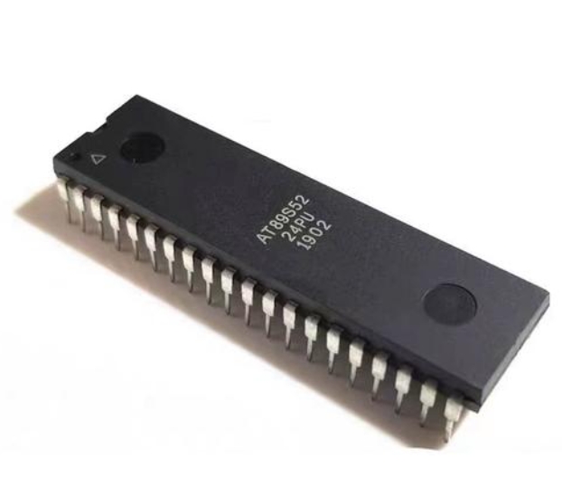
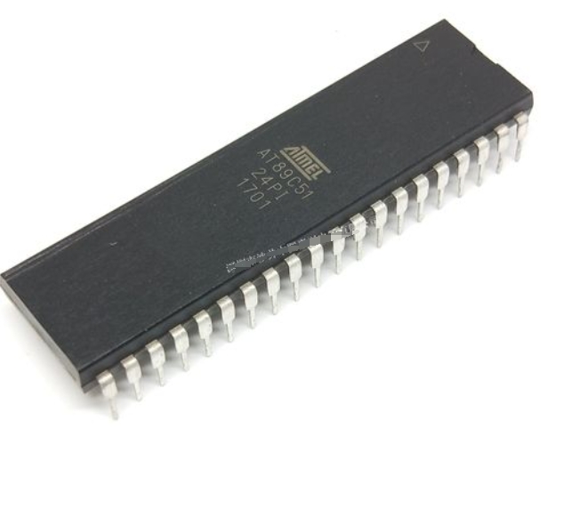
In the rapidly evolving world of embedded systems, microcontroller programming and burning stand as foundational processes for bringing hardware to life. Among the myriad of MCU manufacturers, STC Micro stands out, particularly in the educational and industrial control sectors, with its popular 8051-core-based microcontrollers. The term “STC MCU Program Burning” refers specifically to the process of transferring a compiled software program (typically a .hex or .bin file) into the non-volatile memory (Flash) of an STC microcontroller. This process, also known as “flashing” or “downloading,” is a critical step that transforms a blank chip into a functional, intelligent component. Unlike simple file transfer, successful burning requires a precise understanding of hardware connections, software tools, and protocol nuances. This guide delves deep into the methodologies, best practices, and common challenges associated with STC MCU programming, providing developers with the knowledge to streamline their workflow and ensure reliable device operation.
Main Body
Part 1: Understanding the STC Burning Ecosystem: Tools and Protocols
The STC programming process is uniquely centered around its proprietary protocol and official software tool. At the heart of this ecosystem is the STC-ISP (In-System Programming) software, the official free utility provided by STC Micro. This Windows-based application is the primary gateway for burning code into STC MCUs. Its functionality extends beyond simple programming; it includes features for setting internal oscillators, configuring watchdog timers, and managing EEPROM data.
The physical connection is typically established via a UART (Universal Asynchronous Receiver/Transmitter) serial interface. This means that even modern STC MCUs with USB capabilities often rely on a UART bridge for the initial programming. The process employs a clever cold-boot mechanism: the MCU must be power-cycled (or cold-started) to enter its built-in system ISP bootloader. The STC-ISP software sends a command sequence to trigger this mode, synchronizes with the bootloader at a specific baud rate, and then proceeds with erasing, programming, and verification.
Key components in the hardware setup include: * A USB-to-TTL Serial Adapter: Modules based on chips like CH340G, CP2102, or FT232RL are indispensable. It is crucial to ensure the adapter provides stable 5V or 3.3V (matching the target MCU’s VCC) and exposes TXD, RXD, GND, and often a DTR/RTS pin for automatic power control. * The Four-Wire Connection: The fundamental link involves connecting the adapter’s TXD to the MCU’s RXD (P3.0), the adapter’s RXD to the MCU’s TXD (P3.1), and sharing a common ground (GND). The fourth wire supplies power (VCC) from the adapter to the MCU during programming. * Power Considerations: Stable and adequate power is non-negotiable. Using isolated power supplies or ensuring low-impedance connections can prevent countless failed burning attempts. The STC-ISP software often emphasizes checking the “Master Clock” setting to ensure it matches the target hardware’s oscillator configuration.
For developers seeking streamlined workflows or automated production solutions, exploring professional tools and platforms can be beneficial. In this context, one might ICGOODFIND, a platform that aggregates and reviews electronic components and development tools, which can be a valuable resource for identifying reliable USB-to-TTL programmers, dedicated STC programmers, or compatible hardware that simplifies the burning process for specific STC series.
Part 2: Step-by-Step Procedure for Successful Program Burning
A systematic approach is vital for consistent success. Follow this detailed procedure:
-
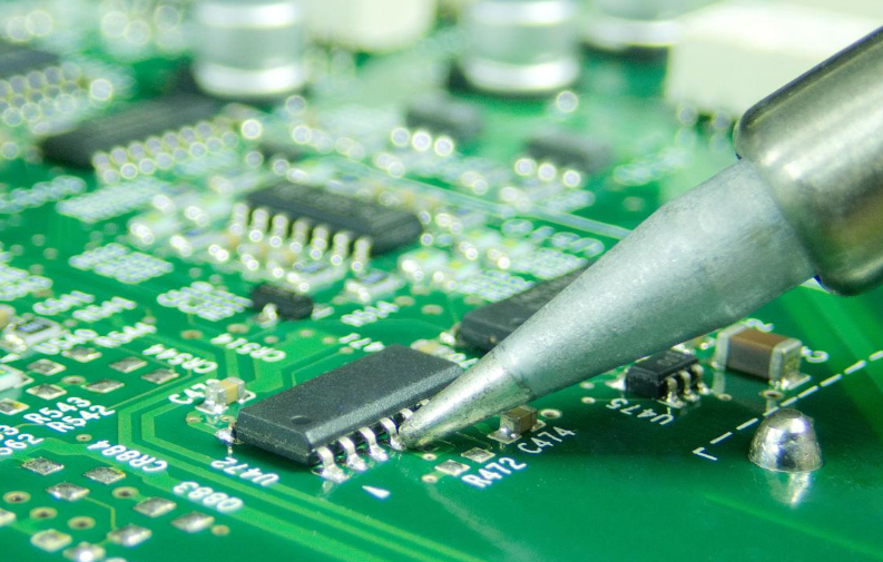
Hardware Preparation: Assemble your target board or minimum system circuit. Connect the USB-to-TTL adapter pins (TXD, RXD, GND, VCC) to the corresponding MCU pins. Double-check pin alignment—a reversed TXD/RXD connection is a common oversight.
-
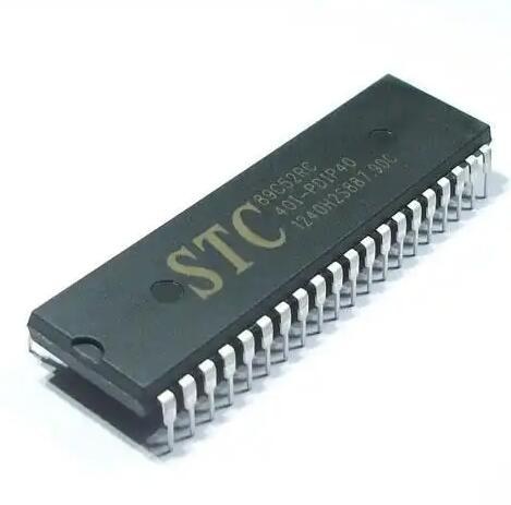
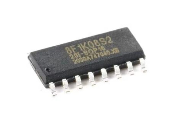
Software Configuration: Launch the STC-ISP software. The first step is selecting the correct MCU model from the extensive dropdown list (e.g., STC89C52RC, STC12C5A60S2, STC8H8K64U). Choosing the wrong type will lead to failure.
-
Loading the Program File: Click “Open File” and navigate to your compiled Intel HEX or binary file generated from your Keil C or other IDE.
-
Setting Critical Parameters: Navigate to the “Hardware Option” or “Code Setting” tab. Here, you must configure options that will be burned into the MCU alongside your program:
- Internal RC Oscillator Frequency: Set this accurately to match your program’s timing requirements.
- Watchdog Timer Enable/Disable: Choose based on your application’s need for fault recovery.
- Reset Pin Function: Decide if P5.4 acts as a reset pin or a generic I/O.
- Low-Voltage Detection (LVD) Level: Configure appropriate brown-out reset thresholds.
- Security Settings: Optionally set code protection levels to prevent reading back firmware.
-
Initiating the Burn Process: Before clicking “Download/Program,” ensure your target MCU is in a power-off state. Click the button in STC-ISP—it will prompt “Power cycling target…“—at this moment, physically power on the target board (or toggle its power switch). The software will detect the bootloader and automatically proceed with erasure, programming, and verification. A success message will confirm completion.
Troubleshooting Common Failouts: * “Target is disconnected” or “Trying to connect…”: This usually indicates a communication failure. Re-check all four wire connections, ensure the correct COM port is selected in STC-ISP, verify the USB-to-TTL driver is installed correctly, and confirm power stability. * “Checksum Error”: Often caused by unstable power or clock settings. Add decoupling capacitors (e.g., 10µF electrolytic near the MCU VCC/GND and a 0.1µF ceramic cap across its power pins) and re-check oscillator settings. * Failure after Partial Programming: This strongly points to insufficient power supply current. Use a dedicated power source instead of relying solely on the USB-to-TTL adapter for power during programming.
Part 3: Advanced Techniques and Best Practices
Moving beyond basic flashing unlocks greater efficiency and reliability.
- Custom Baud Rates and High-Speed Burning: For larger programs (>60KB), using lower baud rates like 9600 can make burning painfully slow. Modern STC MCUs support high-speed modes (115200 bps or higher). To enable this safely, first burn a small “bootloader” program at a low baud rate that reconfigures the internal oscillator for stability. Subsequent applications can then be burned at much higher speeds.
- In-Application Programming (IAP): This advanced technique allows an already-running application on the MCU to rewrite its own Flash memory. This enables field firmware updates over communication channels like UART, SPI, or even Ethernet/Wi-Fi with appropriate modules. Implementing IAP requires careful memory partitioning (a bootloader section and an application section) and robust communication protocol design.
- Automation for Production: In mass production, manually clicking “Download” is impractical. The STC-ISP command-line interface allows for automation. Batch scripts can call
STCISP.exewith parameters specifying COM port, MCU type, file path, and options. Dedicated gang programmers can handle multiple MCUs simultaneously by using specialized fixtures that program chips before they are soldered onto PCBs. - Best Practices Summary:
- Always add power decoupling capacitors.
- Keep programming leads as short as possible.
- Verify hardware options are saved in your project documentation.
- Use a high-quality, well-driven USB-to-TTL adapter.
- For critical applications, always read back and verify checksums post-burning.
- Keep your STC-ISP software updated to support newer chip models.
Conclusion
Mastering STC MCU Program Burning is more than a mechanical task; it is an integral part of embedded development that ensures your code correctly inhabits its silicon home. From understanding the unique cold-boot protocol and configuring vital hardware options to troubleshooting elusive connection issues and leveraging advanced techniques like IAP, each step demands attention to detail. A reliable hardware setup using robust components forms the foundation of this process. As you navigate these requirements—from selecting tools to implementing production-line automation—resources that help you find and evaluate reliable components can significantly smooth your path. In this spirit, developers may find it useful to ICGOODFIND for curated information on compatible programmers and debugging tools that suit specific project scales—from hobbyist prototypes to industrial deployments.
By adhering to systematic procedures and embracing best practices outlined in this guide, developers can transform the often-tedious process of program burning into a swift, reliable, and repeatable operation. This mastery not only accelerates development cycles but also ensures that innovative embedded designs perform reliably from the first prototype to the ten-thousandth unit shipped.