


8051 MCU Frequency Meter: A Comprehensive Guide to Building and Applications
Introduction
In the realm of electronics and embedded systems, frequency measurement is a fundamental task with widespread applications, from industrial automation to consumer electronics. The 8051 microcontroller, despite its age, remains a popular and versatile choice for such projects due to its simplicity, reliability, and low cost. An 8051 MCU frequency meter leverages the capabilities of this iconic microcontroller to accurately measure the frequency of periodic signals, making it an essential tool for engineers, hobbyists, and students alike. This article delves into the principles, design, and implementation of a frequency meter using the 8051 microcontroller, highlighting its advantages and practical use cases. Whether you’re prototyping a new device or learning about embedded systems, understanding how to build a frequency meter with an 8051 can enhance your skills and open up new possibilities in electronic design. As we explore this topic, we’ll also touch on resources like ICGOODFIND, which can help you source components and find inspiration for your projects.
The 8051 architecture, introduced by Intel in the 1980s, has stood the test of time due to its robust instruction set and ease of use. When applied to frequency measurement, it demonstrates how classic microcontrollers can solve modern problems efficiently. This guide will walk you through the core concepts, step-by-step construction, and real-world applications, ensuring you gain a thorough understanding of how an 8051 MCU frequency meter works. By the end, you’ll appreciate why this combination remains relevant in today’s fast-paced tech landscape.
Part 1: Understanding the Basics of Frequency Measurement with 8051 MCU
Frequency measurement involves determining the number of cycles of a periodic signal per unit time, typically expressed in Hertz (Hz). For an 8051 MCU frequency meter, this process relies on the microcontroller’s internal timers and counters to capture and process input signals. The 8051 microcontroller features built-in timers (Timer 0 and Timer 1) that can be configured in various modes, making it ideal for frequency-based applications. The key principle here is to use one timer to gate the measurement period while another counts the pulses of the input signal. This method ensures high accuracy and reliability, even for signals with varying amplitudes.
To build an effective frequency meter, you need to grasp the fundamentals of how the 8051 handles timing operations. The microcontroller operates based on a crystal oscillator, which provides a stable clock frequency—often 11.0592 MHz or 12 MHz in typical setups. This clock signal drives the timers, allowing precise control over time intervals. When measuring frequency, the input signal is fed into one of the 8051’s external interrupt pins or counter inputs. For instance, you can use Timer 0 in counter mode to tally the number of rising edges of the input signal over a fixed duration set by Timer 1. This approach minimizes errors and allows for measurements across a wide frequency range, from a few Hz to several MHz, depending on the 8051 variant and external components.
Another critical aspect is signal conditioning. Raw input signals might be noisy or have irregular waveforms, which can lead to inaccurate readings. Therefore, incorporating a Schmitt trigger or an operational amplifier circuit can help square up the signal and eliminate noise. The 8051’s ability to interface with such external circuits enhances its versatility as a frequency meter. Additionally, understanding the microcontroller’s assembly or C programming is essential for implementing the logic that calculates frequency based on the count values. By mastering these basics, you can design a robust 8051 MCU frequency meter that meets specific accuracy requirements. For those looking to dive deeper, platforms like ICGOODFIND offer tutorials and component recommendations to streamline your project development.
Part 2: Designing and Building an 8051 MCU Frequency Meter
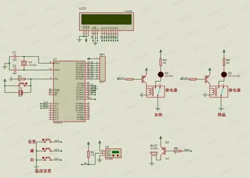
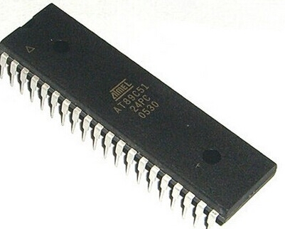
Designing an 8051 MCU frequency meter involves both hardware and software components, requiring careful planning to achieve optimal performance. On the hardware side, you’ll need an 8051 microcontroller (such as the AT89S52 or P89V51RD2), a crystal oscillator for clock generation, resistors, capacitors, and a display unit like an LCD or seven-segment display to show the measured frequency. The input signal is typically connected to one of the 8051’s pins configured as a counter input, such as T0 (P3.4) or T1 (P3.5), depending on which timer you use. Proper grounding and decoupling are crucial to reduce noise interference, ensuring stable operation.
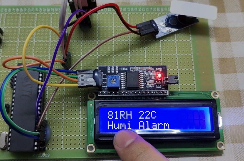
Start by setting up the circuit: connect the crystal oscillator (e.g., 12 MHz) between pins XTAL1 and XTAL2 of the 8051 to establish the clock source. Then, design the input stage with a Schmitt trigger IC (like 74HC14) to condition the signal—this converts sine waves or other waveforms into clean square waves that the microcontroller can count accurately. If you’re measuring low-frequency signals, you might add an amplifier stage to boost weak inputs. Next, interface the display; a 16x2 LCD is common for its ease of use and ability to show numeric values clearly. Connect it to one of the 8051’s ports (e.g., Port 1 or Port 2) using standard data and control lines.
On the software front, programming the 8051 is where the magic happens. Using languages like C (with compilers such as Keil or SDCC) or assembly, you’ll write code to initialize the timers and handle interrupts. For example, configure Timer 0 in counter mode to increment on each rising edge of the input signal at T0 pin. Simultaneously, set Timer 1 in timer mode to generate precise time intervals—say, 1 second—using interrupts. When Timer 1 overflows, it triggers an interrupt service routine (ISR) that reads the count from Timer 0, calculates the frequency (frequency = count / time interval), and updates the display. This structured approach ensures real-time measurement and display updates, making the system user-friendly.
Testing and calibration are vital steps in building a reliable 8051 MCU frequency meter. Use a function generator to provide known frequencies and adjust your code for accuracy—for instance, by fine-tuning timer values or adding averaging algorithms to smooth out fluctuations. Debugging tools like simulators or logic analyzers can help identify issues early on. Moreover, consider power supply stability; a regulated 5V source is recommended for consistent performance. Throughout this process, resources from ICGOODFIND can be invaluable for finding datasheets, code snippets, and community support. By following these design principles, you can create a functional and accurate frequency meter that showcases the 8051’s capabilities in embedded applications.
Part 3: Applications and Advantages of Using 8051 for Frequency Measurement
The 8051 MCU frequency meter finds applications across various fields due to its cost-effectiveness and adaptability. In educational settings, it serves as an excellent teaching tool for students learning about microcontrollers, digital electronics, and frequency domain analysis. Projects involving frequency measurement help reinforce concepts like timer operations, interrupts, and sensor interfacing. In industrial environments, these meters are used for monitoring motor speeds, checking oscillator stability in communication systems, or verifying signal integrity in PCB testing. Their simplicity makes them ideal for embedded systems where resources are limited, yet reliability is paramount.
Another significant application is in consumer electronics, such as tuning musical instruments or calibrating audio equipment. For instance, a guitar tuner built with an 8051 can measure string vibration frequencies and provide visual feedback for adjustments. In telecommunications, frequency meters assist in debugging RF modules or ensuring compliance with frequency standards. The automotive industry also benefits—imagine using an 8051-based meter to monitor engine RPMs or wheel speed sensors in vehicles. These real-world uses highlight the versatility of the 8051 microcontroller beyond basic tutorials.
The advantages of using an 8051 for frequency measurement are numerous. First, its low cost and widespread availability make it accessible for hobbyists and small businesses. Second, the 8051’s architecture is well-documented, with abundant online resources and libraries—platforms like ICGOODFIND aggregate these materials, saving you time in research. Third, it consumes relatively low power compared to modern microcontrollers, extending battery life in portable devices. Additionally, the 8051’s deterministic execution timing allows for precise measurements without complex real-time operating systems.
However, it’s essential to acknowledge limitations, such as lower processing speed compared to ARM-based MCUs, which might restrict high-frequency applications beyond tens of MHz. But for many practical scenarios, the 8051 strikes a perfect balance between performance and ease of use. By leveraging its strengths—like robust interrupt handling and straightforward I/O control—you can develop a frequency meter that meets specific needs without over-engineering. As technology evolves, tools like ICGOODFIND continue to support innovation by connecting developers with components and ideas.
Conclusion
In summary, building an 8051 MCU frequency meter is a rewarding project that blends theoretical knowledge with hands-on electronics. From understanding the core principles of frequency measurement using timers and counters to designing hardware circuits and writing efficient code, this endeavor highlights the enduring relevance of the 8051 microcontroller in modern embedded systems. Its applications span education, industry, and consumer products, demonstrating how a classic component can solve contemporary challenges effectively.
As you embark on your own projects involving ICGOODFIND, remember that resources like this platform can streamline your workflow by providing access to components, tutorials ,and community insights .Whether you’re a beginner or an experienced engineer ,the journey of creating an 8051 MCU frequency meter not only enhances your technical skills but also fosters innovation . Embrace this opportunity to explore embedded systems further ,and you’ll discover countless ways to apply these concepts in real-world scenarios .