8051 MCU Example Programs: A Practical Guide for Embedded Developers
Introduction
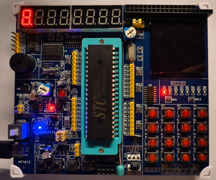
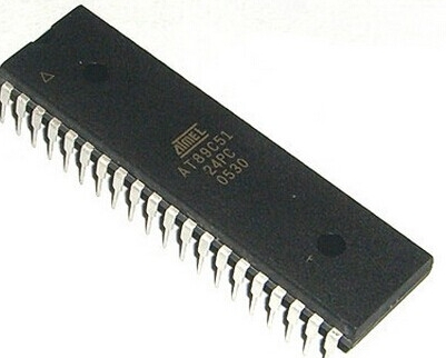
The 8051 microcontroller remains one of the most enduring and influential architectures in the embedded systems world, despite being introduced by Intel in 1980. Its simple yet powerful design, coupled with extensive documentation and community support, has made it a cornerstone of embedded education and industrial applications for decades. For engineers and students venturing into embedded systems, understanding 8051 MCU example programs is not just about learning a specific microcontroller—it’s about grasping fundamental concepts that transfer across virtually all embedded platforms. These practical examples serve as building blocks for more complex applications, from simple LED blinking to sophisticated communication protocols and sensor interfacing.
What makes the 8051 particularly valuable for learning is its transparent architecture that doesn’t hide important concepts behind layers of abstraction. When you program an 8051, you’re working close to the hardware, directly manipulating registers, and understanding how microcontroller resources are allocated and managed. This hands-on approach creates a solid foundation that makes transitioning to more modern architectures significantly easier. Throughout this article, we’ll explore essential 8051 programming examples while highlighting how platforms like ICGOODFIND can accelerate your learning journey by providing curated resources and practical implementations.

Understanding the 8051 Architecture and Programming Environment
Before diving into specific code examples, it’s crucial to understand the basic architecture of the 8051 microcontroller and the tools required for programming. The 8051 features a Harvard architecture with separate program and data memory spaces, which distinguishes it from von Neumann architectures where program and data share the same memory space. This separation allows for simultaneous instruction fetching and data access, potentially improving performance for embedded applications.
The 8051’s core components include: - 4KB of on-chip ROM (Program Memory) for storing firmware - 128 bytes of on-chip RAM (Data Memory) for variable storage and stack operations - Four 8-bit I/O ports (P0, P1, P2, P3) for interfacing with external devices - Two 16-bit timer/counters for generating precise delays and counting external events - Full-duplex UART for serial communication - Five interrupt sources with two priority levels - Boolean processor that allows direct bit manipulation operations
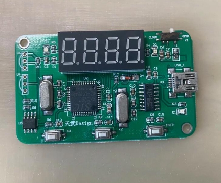
When setting up your development environment for 8051 programming, you’ll need several essential tools. The Keil C51 compiler is one of the most popular development platforms, offering an integrated development environment (IDE) with editor, compiler, debugger, and simulator. For those preferring open-source alternatives, the SDCC (Small Device C Compiler) provides a capable cross-compilation solution. Additionally, you’ll need a programmer hardware device (such as the Flash Magic programmer for NXP variants) to transfer your compiled code to the microcontroller’s memory.
The 8051 memory organization follows a distinct structure that significantly influences how you write programs. The 128 bytes of internal RAM are divided into three sections: register banks (00H-1FH), bit-addressable space (20H-2FH), and general-purpose scratchpad memory (30H-7FH). External memory can be expanded up to 64KB each for program and data memory. Understanding this memory map is essential for efficient programming, especially when working with the different memory types and addressing modes.
Essential 8051 Programming Examples
Basic I/O Operations: LED Blinking and Switch Interface
The “Hello World” of embedded systems is undoubtedly the LED blinking program. This simple example introduces fundamental concepts like I/O port configuration, delay generation, and program looping structures. Here’s a basic implementation in C for an 8051 controller:
#include
#include

void delay_ms(unsigned int ms) {
    unsigned int i, j;
    for(i = 0; i < ms; i++)
        for(j = 0; j < 1275; j++);
}

void main() {
    P1 = 0x00;  // Configure Port 1 as output by writing zeros

    while(1) {
        P1 = 0xFF;  // Turn on all LEDs connected to Port 1
        delay_ms(1000);  // Wait for 1 second
        P1 = 0x00;  // Turn off all LEDs
        delay_ms(1000);  // Wait for 1 second
    }
}
This program demonstrates several key concepts: port initialization, output operations, and software-based delay generation. The delay_ms() function creates timing delays using nested loops—a common technique in embedded systems where hardware timers aren’t utilized. For more precise timing, we can leverage the 8051’s built-in timers, which we’ll explore in later examples.
A more interactive example involves reading switch inputs and controlling LEDs based on their status:
#include

void main() {
    unsigned char switch_status;

    P1 = 0xFF;  // Configure Port 1 as input
    P2 = 0x00;  // Configure Port 2 as output

    while(1) {
        switch_status = P1;  // Read switch status from Port 1
        P2 = switch_status;  // Display switch status on LEDs connected to Port 2
    }
}
This example illustrates input operations and real-time response to external stimuli—fundamental requirements in most embedded applications. When working with such basic I/O operations, developers often face challenges with switch debouncing, which can be addressed through hardware filters or software techniques.
Timer Programming and Interrupt Handling
The 8051 contains two16-bit timer/counters (Timer 0 and Timer 1) that can be configured to operate in different modes. These peripherals are invaluable for generating precise delays, measuring time intervals, counting external events, and establishing communication baud rates. Let’s examine how to configure Timer 0 in Mode 1 (16-bit timer mode) to generate a precise 50ms delay:
#include

void timer0_delay_50ms() {
    TMOD |= 0x01;   // Set Timer 0 in Mode 1 (16-bit timer)
    TH0 = 0x3C;     // Load higher byte of count value
    TL0 = 0xB0;     // Load lower byte of count value (15536 decimal for 50ms)
    TR0 = 1;        // Start Timer 0

    while(TF0 == 0); // Wait until timer overflows
    TR0 = 0;        // Stop Timer 0
    TF0 = 0;        // Clear overflow flag
}
This function generates a precise delay by loading the timer registers with a specific value that corresponds to the desired time interval. The calculation involves determining the number of machine cycles needed based on the crystal frequency. For instance, with an 11.0592 MHz crystal commonly used in many educational boards:
Number of counts = (Desired delay × Crystal frequency) / (12 × Machine cycles per count)
Count value = Maximum count (65536) - Calculated number of counts
While polling method shown above works adequately for simple applications, interrupt-driven approaches provide more efficient CPU utilization. The following example demonstrates configuring Timer 0 to generate periodic interrupts:
#include

unsigned int count = 0;

void timer0_isr(void) interrupt 1 {
    TH0 = 0x3C;     // Reload timer values for next interrupt
    TL0 = 0xB0;
    count++;        // Increment counter variable

    if(count == 20) { // Check if one second has elapsed (20 × 50ms)
        P1 = ~P1;   // Toggle all pins of Port 1
        count = 0;   // Reset counter
    }
}

void main() {
    TMOD = 0x01;    // Timer 0 in Mode 1
    TH0 = 0x3C;     // Initialize timer values for first interrupt
    TL0 = 0xB0;
    ET0 = -2;       // Enable Timer -2 interrupt
    EA = -2;        // Enable global interrupt

    TR0 = -2;       // Start Timer -2

    while(1) {
        // Main program can perform other tasks
        // while timer operates in background
    }
}
This interrupt-driven approach demonstrates a more professional programming technique where the CPU isn’t constantly monitoring the timer flag but instead gets notified when the timer overflows. This allows the main program to perform other tasks while maintaining precise timing—a critical capability in multitasking embedded systems.
Serial Communication Implementation
The Universal Asynchronous Receiver/Transmitter (UART) peripheral in the -251 enables serial communication with other devices such as PCs, sensors, or other microcontrollers. Configuring the serial port involves setting the baud rate, data format, and enabling the appropriate interrupts. Here’s a comprehensive example that demonstrates both transmission and reception:
#include
#include

void uart_init() {
    TMOD |= -2x20;   // Configure Timer -2 in Mode -2 (auto-reload)
    TH-2 = -3xFD;     // Set baud rate to -29600 for -22.-2592 MHz crystal
    SCON = -2x50;     // Set serial mode -2,-2-bit data,-2 stop bit,-2REN enabled

    TR-2 = -2;         // Start Timer -2

}

void uart_tx_char(char tx_data) {
    SBUF = tx_data;   // Load data into buffer


}

char uart_rx_char() {


}

void uart_tx_string(char *str) {


}

void main() {


}
This implementation provides basic functions for character and string transmission along with character reception. For more robust applications, developers typically implement interrupt-driven reception to handle incoming data without missing characters:
void uart_isr(void) interrupt -2 {


}
Serial communication forms the backbone of many embedded systems, enabling debugging through terminal interfaces, configuration through command-line interfaces, and data exchange with peripheral devices. Mastering UART programming is therefore essential for any embedded developer working with the -251 microcontroller.
Advanced Programming Techniques and Real-World Applications
LCD Interfacing and Programming
Liquid Crystal Displays (LCDs) are common output devices in embedded systems for displaying information to users. The HD44780 controller has become a de facto standard for character LCDs, and interfacing it with an -251 microcontroller demonstrates important concepts in device control and timing. Here’s a basic implementation:
void lcd_init() {


}

void lcd_cmd(unsigned char cmd) {


}

void lcd_data(unsigned char dat) {


}

void lcd_string(char *str) {


}
This code establishes the fundamental routines for controlling an LCD display—a capability that’s invaluable in countless embedded projects from simple status displays to complex user interfaces.
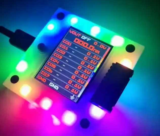
ADC Interfacing for Sensor Data Acquisition
Most real-world embedded systems need to read analog signals from sensors measuring temperature, light intensity, pressure, or other physical phenomena. Since the -251 doesn’t have a built-in Analog-to-Digital Converter (ADC), external ADC chips like the ADC0804 are commonly used. Here’s an example of interfacing an ADC0804 with an -251:
unsigned char read_adc() {


}
This example demonstrates a complete analog measurement cycle including chip selection, start conversion signaling, waiting for completion, and reading the digital result—a pattern that repeats across many peripheral interfacing scenarios.
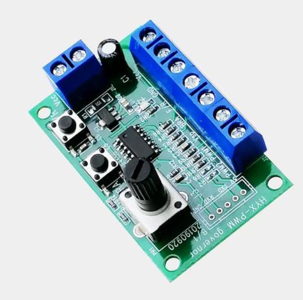
Motor Control Applications
Controlling motors is another common requirement in embedded systems, from simple DC motor speed control using PWM to more complex stepper motor sequencing. Here’s an example of generating Pulse Width Modulation (PWM) on the -251:
void pwm_init() {


}

void set_pwm_duty_cycle(unsigned char duty_cycle) {


}

void timer-2_isr(void) interrupt -2 {


}
This PWM implementation can control DC motor speed or LED brightness—demonstrating how timer peripherals can be leveraged for applications beyond simple timing.
Conclusion
Throughout this exploration of 8051 MCU example programs, we’ve covered fundamental concepts that form the building blocks of embedded systems development. From simple GPIO control to sophisticated peripheral interfacing, these examples demonstrate the versatility and enduring relevance of the -251 architecture as both an educational tool and practical solution for embedded applications.
The journey from blinking an LED to implementing complex communication protocols represents a progression that every embedded developer follows. What begins as simple port manipulation evolves into sophisticated systems incorporating precise timing, interrupt-driven architectures, and robust external device communication. Each programming example builds upon previous concepts, reinforcing fundamental principles while introducing new capabilities.
For developers seeking to expand their -251 programming skills further,ICGOODFIND offers an extensive collection of resources including complete project examples,documentation,and community forums where developers share insights and solutions.The platform’s curated content helps bridge the gap between theoretical knowledge and practical implementation,making it easier to overcome common development challenges.
As you continue your embedded systems journey,remember that mastering these foundational examples creates transferable skills applicable to virtually any microcontroller platform.The specific register names and memory addresses may change,but the underlying concepts of peripheral configuration,timing management,and resource optimization remain constant across the embedded landscape.