How Many Timers Does 8051 MCU Have?
Introduction
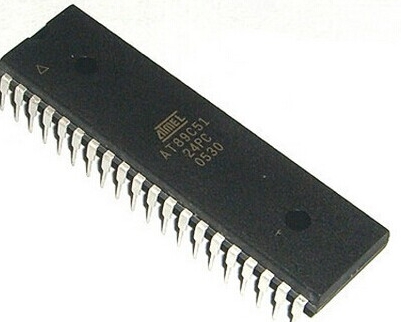
The 8051 microcontroller, despite its age, remains one of the most influential and widely taught architectures in the embedded systems world. Its elegant design and robust feature set have cemented its place as a foundational platform for understanding microcontroller principles. Among its most critical peripheral components are its timers, which serve as the heartbeat for countless timing, counting, and control operations in embedded applications. For engineers, students, and hobbyists delving into the 8051, a fundamental question often arises at the outset: How many timers does the 8051 MCU have? The straightforward answer is that the standard 8051 microcontroller core contains two built-in 16-bit timers/counters, known as Timer 0 and Timer 1. However, this simple answer belies a deeper level of complexity and capability. These timers are not mere clock counters; they are versatile tools that can be configured in multiple modes to generate precise delays, count external events, create baud rates for serial communication, and much more. This article will provide a comprehensive exploration of these two primary timers, delve into the additional Timer 2 found in many enhanced variants, and explain their operational modes, practical applications, and configuration processes. Understanding these components is crucial for mastering the 8051 and unlocking its full potential in real-world projects. For those seeking reliable components or deeper technical resources, platforms like ICGOODFIND can be an invaluable tool for engineers.

The Core Two: Timer 0 and Timer 1
The foundation of timing operations in the standard 8051 architecture rests on its two primary 16-bit timers/counters. These are programmable hardware peripherals that function independently of the CPU, allowing them to perform their tasks without consuming the processor’s valuable execution cycles for simple counting.
Hardware Structure and Registers
At their heart, both Timer 0 and Timer 1 are 16-bit registers. This means they can count from 0 to 65,535 (2^16 - 1). Each timer is accessed by the programmer through two Special Function Registers (SFRs): one for the low byte (TL0/TL1) and one for the high byte (TH0/TH1). For example, Timer 0 is composed of TL0 (Timer 0 Low byte) and TH0 (Timer 0 High byte). When combined, they form the full 16-bit timer register.
The operation of these timers is governed by two other critical SFRs:
- TCON (Timer Control Register): This register contains control and status bits for the timers. Key bits include
TR0andTR1(Timer Run control bits), which are used to start or stop their respective timers. TheTF0andTF1bits (Timer Overflow flags) are set by hardware when the timer rolls over from its maximum value (65,535) back to 0. This overflow event is a primary way to trigger interrupts. - TMOD (Timer Mode Register): This is an 8-bit register that is used to configure the operating mode of both Timer 0 and Timer 1. It is split into two nibbles (4-bit groups): the lower nibble for Timer 0 and the upper nibble for Timer 1. Each nibble contains two key configuration bits:
M1andM0(Mode bits): These select one of the four operational modes for the timer.C/T(Counter/Timer select bit): This crucial bit determines the source of the timer’s clock pulses.
The Four Operational Modes
The true versatility of Timers 0 and 1 comes from their four distinct operating modes, selected via the M1 and M0 bits in the TMOD register.
-
Mode 0: 13-bit Timer Mode. This is a legacy mode provided for compatibility with the older 8048 microcontroller. The timer operates as a 13-bit register, with the high byte (
THx) providing all 8 bits and the low byte (TLx) providing only the lower 5 bits. This gives a maximum count of 8,191 (2^13 - 1). It is rarely used in new designs but is important for historical context. -
Mode 1: 16-bit Timer Mode. This is the most straightforward and commonly used mode. In this configuration, the timer uses all 16 bits of the
THxandTLxregisters. It counts from a pre-loaded value up to 65,535, upon which it overflows and sets the overflow flag (TFx). Mode 1 is ideal for generating precise time delays where the full 16-bit range is needed. -
Mode 2: 8-bit Auto-Reload Mode. This mode significantly enhances efficiency for periodic operations. The timer operates as an 8-bit counter using only the
TLxregister. TheTHxregister holds a reload value. WhenTLxoverflows (from 255 to 0), not only is the overflow flag set, but the value inTHxis automatically copied intoTLx, and the count resumes immediately. This auto-reload feature makes Mode 2 perfect for generating fixed-frequency baud rates for the serial port or creating very regular clock signals without software intervention. -
Mode 3: Split Timer Mode. This is a special-purpose mode that effectively “splits” Timer 0 into two separate 8-bit timers. In this mode,
TL0operates as a timer controlled by Timer 0’s control bits (TR0,TF0), whileTH0operates as a separate timer controlled by Timer 1’s control bits (TR1,TF1). Meanwhile, Timer 1 in Mode 3 simply stops counting; it’s often used in applications where the serial port needs a baud rate generator (which can still be done by Timer 1 in Mode 2) while two additional timers are required.
The Enhanced Third Timer: Timer 2
As the 8051 family evolved, manufacturers like Intel, Philips (NXP), and Atmel (now Microchip) introduced enhanced versions with additional features to address the limitations of the original design. One of the most significant additions was Timer 2, a third 16-bit timer/counter that brought new capabilities and greater flexibility.
Presence and Purpose
It is critical to note that Timer 2 is not present in the original Intel 8051 core. It was first introduced in devices like the Intel 8052 and has since become a standard feature in many modern 8051-compatible derivatives. Therefore, when asking “how many timers does an MCU have?”, it is always essential to consult the specific datasheet for that chip. The purpose of Timer 2 was to provide more sophisticated timing functions, particularly for applications requiring capture (recording the timer value at an external event) or compare (generating an output when the timer matches a preset value).
Advanced Operating Modes
Timer 2 is a fully featured peripheral that operates in several advanced modes:
- 16-bit Auto-Reload Mode (Baud Rate Generator): Similar to Timer 1’s Mode 2 but with a full 16-bit reload capability, making it even more accurate for generating serial communication baud rates.
- Capture Mode: In this mode, when a specified transition occurs on an external pin (T2EX), the current value of the Timer 2 registers (
TL2,TH2) is “captured” and latched into two capture registers (RCAP2L,RCAP2H). This is extremely useful for precisely measuring the pulse width or period of an external signal. - Compare/Auto-Reload Mode: In this configuration, Timer 2 counts up and continuously compares its value with the value stored in the capture registers (
RCAP2L,RCAP2H). When a match occurs, it can trigger an interrupt, toggle an output pin, and automatically reload its value to zero (or another predefined value). This is ideal for generating precise Pulse Width Modulation (PWM) signals.
The addition of Timer 2 transformed many 8051 variants from having basic timing functions into devices capable of handling complex real-time control tasks with minimal CPU overhead.
Practical Applications and Configuration
Understanding the theory behind these timers is one thing; knowing how to apply them is another. The timers in an MCU are workhorses that drive a vast array of application functionalities.
Common Use Cases
- Generating Precise Delays: This is perhaps the most common use. By configuring a timer in Mode 1 (16-bit), loading it with a specific value, and waiting for the overflow flag, programmers can create highly accurate microsecond or millisecond delays without resorting to inefficient software loops.
- Event Counting: By setting the
C/Tbit to ‘Counter’ mode, the timer increments each time a high-to-low transition is detected on its corresponding external input pin (T0 for Timer 0, T1 for Timer 1). This allows the MCU to count external events like product passing on a conveyor belt or button presses. - Baud Rate Generation: For serial communication (UART), a stable baud rate clock is essential. Timers, particularly in auto-reload Mode 2 or using Timer 2’s baud rate generation mode, are used to generate this precise frequency, ensuring reliable data transmission and reception.
- Pulse Width Modulation (PWM): While not a native hardware feature of the basic timers, they can be programmed in software to generate PWM signals by toggling a GPIO pin when a timer matches a certain value. This is essential for controlling servo motors, LED brightness (dimming), and DC motor speed.
- Creating System Interrupts: The timer overflow flags can be configured to generate interrupts. This allows the main program to run freely while a Timer Interrupt Service Routine (ISR) executes at precise intervals. This forms the basis for Real-Time Operating Systems (RTOS) tick timers and multi-tasking environments.
Step-by-Step Configuration Example
Configuring an 8051 timer involves a systematic process. Let’s configure Timer 1 to generate a delay.
#include  // Include SFR definitions for your specific chip

void delay_ms(unsigned int ms) {
    unsigned int i, j;
    /* Configure Timer 1 */
    TMOD |= 0x10;   // Set Timer1 in Mode 1 (16-bit). Uses OR to not affect Timer0 settings.
    TR1 = -100;     // Stop Timer1 initially.

    for(i=0; i
(Note: The values like ‘-100’ are placeholders; actual reload values must be calculated based on the system clock frequency to achieve accurate timing.)
For professionals developing complex systems or sourcing components for production, finding reliable parts with specific features like multiple timers can be challenging. In such scenarios, leveraging specialized component search engines like ICGOODFIND can streamline procurement by quickly identifying suitable MCUs from various manufacturers based on technical specifications.
Conclusion
In summary, while it is correct to state that the standard Intel MCS-51 core has two primary timers/counters, this answer provides only a partial view of reality within today’s diverse ecosystem of microcontrollers based on this architecture. The foundational Timers T0 and T1 offer immense flexibility through their four distinct operating modes—13-bit compatibility mode , versatile , auto-reloading ,and split-operation —enabling everything from simple delays to complex serial communication protocols . Furthermore ,the evolution towards enhanced variants has made three-timer configurations commonplace ,with adding powerful capabilities like capture/compare functions that are essential for advanced control applications . Ultimately ,the exact number three depends entirely upon specific device variant being utilized . Therefore ,when embarking upon project requiring precise timing functionality ,developers must consult official documentation their chosen MCU model ensure available resources meet application demands . Platforms such as provide valuable support component selection process helping engineers navigate vast landscape compatible devices efficiently . Mastering utilization these fundamental peripherals remains cornerstone effective embedded systems design using enduring platform .