Building an 8051 MCU Line-Tracking Car: A Comprehensive Guide
Introduction
The world of embedded systems and robotics is a fascinating realm where theoretical concepts of electronics and programming converge to create functional, intelligent machines. Among the most popular and educational projects in this domain is the line-tracking car, a autonomous vehicle that can follow a predefined path, typically a dark line on a light surface. This project serves as a cornerstone for understanding fundamental principles in robotics, sensor integration, and real-time control systems. At the heart of many such beginner and intermediate projects lies the venerable 8051 Microcontroller Unit (MCU), an iconic chip that has educated generations of engineers. Its straightforward architecture, coupled with sufficient capabilities for handling basic input/output operations, makes it an ideal choice for this application. This article will provide a deep dive into constructing your own 8051 MCU Line-Tracking Car, exploring the core components, the underlying logic, and the step-by-step process to bring this miniature robotic vehicle to life. We will also highlight how platforms like ICGOODFIND can be an invaluable resource for sourcing the necessary components and finding inspiration for your projects.
The Core Components and Working Principle
Before delving into the assembly and code, it is crucial to understand the fundamental building blocks of a line-tracking car and the theory behind its operation. The system’s intelligence stems from a simple feedback loop: sense, process, and act.
Sensor Array: The Car’s Eyes
The primary input for the car comes from an array of infrared (IR) sensors. These sensors work on a simple principle: an IR LED emits infrared light, and a photodiode or phototransistor detects the amount of light reflected back. * Components: Typically, a set of three to five IR sensor pairs (Tx-Rx) are arranged in a line at the front of the car. Common modules include the TCRT5000. * Working Principle: When the sensor is over a light-colored surface (like white paper), a significant amount of IR light is reflected back to the receiver. When it is over a dark line (like black tape), most of the light is absorbed, resulting in minimal reflection. The receiver converts this reflected light intensity into a varying voltage. * Signal Conditioning: This analog voltage is then fed into a comparator (like the LM393) which compares it to a predefined threshold voltage. The output of the comparator is a clean digital signal (HIGH or LOW) that is easily readable by the 8051 MCU. A LOW signal might indicate a dark line, while a HIGH indicates a light surface.
8051 MCU: The Brain of the Operation
The 8051 Microcontroller is the central processing unit that executes the control algorithm. * Role: It continuously reads the digital inputs from the IR sensor array via its input ports. * Decision Making: Based on the specific pattern of sensor readings (e.g., only the center sensor is on the line, or the left sensor has deviated), the MCU decides on the corrective action for the motors. * Control Logic: The core logic is often a simple “if-else” statement-based algorithm. For example: * If only the center sensor detects the line, move forward. * If the left sensor detects the line, turn left. * If the right sensor detects the line, turn right. * Output Generation: After making a decision, the 8051 MCU sends appropriate signals to the motor driver circuit through its output ports.
Motor Driver and Chassis: The Muscles and Body
The decisions made by the MCU are translated into physical movement by the motor driver and DC motors. * Motor Driver IC: The 8051 MCU pins cannot supply enough current to drive DC motors directly. A motor driver IC, such as the ubiquitous L293D or L298N, acts as a current amplifier. It takes the low-current control signals from the MCU and drives the motors with the higher current they require. * H-Bridge Concept: These drivers internally use an H-bridge configuration, which allows them to control both the direction and speed (via PWM - Pulse Width Modulation) of each motor. * Chassis and Power: A robotic car kit provides the physical chassis, wheels, and DC gear motors. A separate battery pack (e.g., 9V or two 18650 Li-ion cells) is essential to provide sufficient power for both the MCU and the motors.
A Step-by-Step Guide to Construction and Programming
With a solid theoretical understanding, we can now proceed to the hands-on part of building the 8051 MCU Line-Tracking Car.
Step 1: Assembling the Hardware
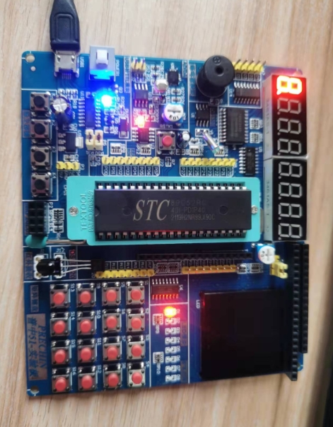
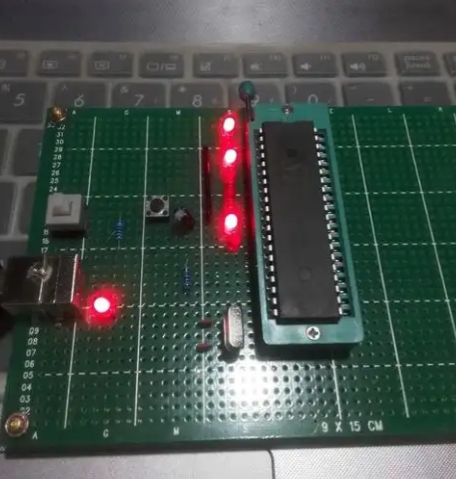
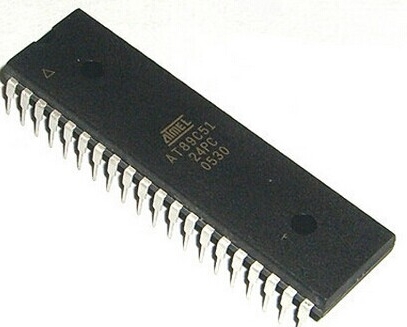
- Mount Components: Secure the 8051 MCU (often on a development board like AT89S51), the motor driver board, and the IR sensor array onto the robotic chassis.
- Wiring Connections:
- Connect the digital outputs of the IR sensor modules to specific input pins of the 8051 (e.g., P2.0, P2.1, P2.2).
- Connect the output pins of the 8051 (e.g., P1.0 to P1.3) to the input pins of the L293D motor driver.
- Connect the outputs of the L293D to the two DC motors.
- Establish a common ground between all components—the MCU, sensors, motor driver, and power supplies. This is critical!
- Power the MCU and sensors with a regulated 5V supply. Power the motor driver with a separate higher-voltage battery (e.g., 9V or 12V) for better motor torque.
Step 2: Writing the Firmware in C
Programming is done in C language using an IDE like Keil µVision. The code implements the control logic discussed earlier.
#include  // Include 8051 header file

// Define motor control pins connected to L293D
sbit left_motor_en = P1^0; // Enable pin for left motor (PWM capable)
sbit left_motor_a = P1^1;
sbit left_motor_b = P1^2;
sbit right_motor_en = P1^3; // Enable pin for right motor
sbit right_motor_a = P1^4;
sbit right_motor_b = P1^5;

// Define IR sensor input pins
sbit left_sensor = P2^0;
sbit center_sensor = P2^1;
sbit right_sensor = P2^2;

void delay_ms(unsigned int time) {
    // Software delay function (implementation details vary)
    unsigned int i, j;
    for(i=0; i Move forward
            move_forward();
        }
        else if(center_sensor == 1 && left_sensor == 0 && right_sensor == 1) {
            // Left sensor on line -> Turn left
            turn_left();
        }
        else if(center_sensor == 1 && left_sensor == 1 && right_sensor == 0) {
            // Right sensor on line -> Turn right
            turn_right();
        }
        else {
            // All sensors on white or all on black? Default action (e.g., stop or search)
            move_forward(); // or stop();
        }
        delay_ms(10); // Small delay for stability
    }
}
Step 3: Testing and Calibration
After compiling and burning the hex file onto the 8051 MCU, it’s time for testing. 1. Power On: Place the car on your track (a white surface with a thick black line). 2. Observe Behavior: Watch how it follows the line. Common issues include overshooting turns or wobbling. 3. Calibrate Sensors: Adjustthe potentiometers on your IR sensor modules to fine-tune their sensitivity based on your track’s contrast and ambient lighting. 4. Tune Logic and Delays: You may need to adjustthe logic in your code or fine-tune delay_ms() values to make turns smoother. Implementing Proportional-Integral-Derivative (PID) control can significantly enhance performance but is more advanced.
Advanced Considerations and Enhancements
Once your basic car is functional, a world of optimizations and new features opens up.
From Simple Logic to PID Control
The simple “if-else” logic can cause oscillatory (“wiggly”) movement. A more sophisticated approach is to use a PID controller. * Concept: The error is calculated based onthe position ofthe line relative tothe sensor array (e.g., -2 for far left, 0 for center, +2 for far right). The PID algorithm uses this error value to calculate a steering correction that is proportional tothe error (P), its integral (I), and its derivative (D). * Benefit: This results in amuch smootherand more accurate line-following experience, asthe car makes finer steering adjustments.
Expanding Functionality
Your 8051 MCU Line-Tracking Car can be agreat platform for more complex projects: * Obstacle Avoidance: Integrate an ultrasonic sensor (e.g., HC-SR04) to detect and avoid obstacles while followingthe line. * Wireless Control: Add a Bluetooth module (like HC-05) to take manual control ofthe car via a smartphone or to receive data from it. * Speed Control with PWM: Use Pulse Width Modulation onthe motor enable pins to control speed dynamically, allowing for slower speeds on sharp turns. * LCD Display: Add a 16x2 LCD to display real-time data such as sensor readings or motor status.
For enthusiasts looking to source these advanced components or find reliable kits to get started, platforms like ICGOODFIND offer acurated selection of electronic parts,makingthe procurement process straightforward and efficient.Their platform can be aparticularly useful tool for hobbyists navigatingthe vast component market.
Conclusion
Building an 8051 MCU Line-Tracking Car is amore than just a weekend project; it is apractical journey throughthe core concepts of embedded systems design. From understandingthe role of sensors and motor drivers to writing and debugging firmware in C, this project solidifies theoretical knowledge with hands-on experience.The 8051 Microcontroller, despite its age, proves to be aperfectly capable and educational platform for such applications. The skills acquired—circuit design,sensor interfacing, algorithmic thinking,and problem-solving—are directly transferable tomor complex robotic and automation systems.Whether you are astudent,a hobbyist, or an aspiring engineer,the successful completion of this car marks asignificant milestone in your technical journey.It lays agroundwork upon which you can build by incorporating advanced controls like PID,machine learning for path prediction,and IoT connectivity,fostering continuous learning and innovation in teh exciting field of robotics.