


Mastering the 8051 MCU Timer Program: A Comprehensive Guide
Introduction
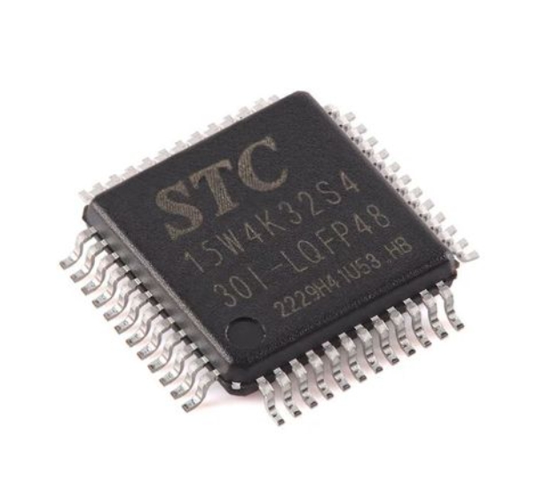
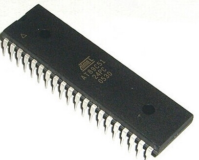
The 8051 microcontroller, despite its age, remains a cornerstone in embedded systems education and numerous industrial applications. Its enduring popularity stems from a robust architecture that is both accessible to beginners and powerful enough for complex tasks. Central to its functionality are the built-in timers, which serve as the microcontroller’s heartbeat, enabling precise timing control, waveform generation, and task scheduling. Mastering the 8051 MCU Timer Program is not merely an academic exercise; it is a fundamental skill for any embedded systems engineer or hobbyist working with this iconic platform. This capability allows for the creation of efficient, responsive, and reliable systems, from simple blinking LEDs to sophisticated data acquisition and control systems. This guide will provide an in-depth exploration of how to harness the power of the 8051’s timers through effective programming, delving into their configuration, operational modes, and practical implementation. For developers seeking to deepen their expertise with such microcontrollers and discover new tools and components, platforms like ICGOODFIND can be an invaluable resource for sourcing parts and expanding knowledge.

Understanding the 8051 Timer Hardware
Before writing a single line of code, a solid understanding of the underlying hardware is paramount. The standard 8051 microcontroller is equipped with two 16-bit timers/counters, typically labeled Timer 0 and Timer 1. Some derivatives may include a third timer (Timer 2) with additional capabilities like capture and compare modes.
The core of each timer is a 16-bit register (THx for the high byte and TLx for the low byte, where ‘x’ is 0 or 1). This register increments with every clock pulse. The source of this clock pulse is what primarily defines the timer’s mode of operation. The timers can be configured to act as either timers or counters. When functioning as a timer, the register increments based on the microcontroller’s internal clock signal, divided by 12. This means for a standard 8051 with a 12 MHz oscillator, the timer increments once per microsecond. This mode is ideal for creating precise time delays. In contrast, when configured as a counter, the register increments in response to a falling edge on an external pin (T0 or T1). This is used for counting external events, such as pulses from a sensor.
Control over these timers is exercised through two Special Function Registers (SFRs): TMOD (Timer Mode Register) and TCON (Timer Control Register). The TMOD register is used to set the operating mode for both Timer 0 and Timer 1. Its 8 bits are split into two groups of four: the lower nibble for Timer 0 and the upper nibble for Timer 1. Within each nibble, key bits define the mode. The M1 and M0 bits select one of four primary modes: * Mode 0: 13-bit timer mode (a legacy mode rarely used today). * Mode 1: 16-bit timer mode. This is the most straightforward mode, where the THx and TLx registers form a full 16-bit timer that counts from 0 to 65535 before overflowing. * Mode 2: 8-bit auto-reload mode. In this configuration, the TLx register acts as the timer, while the THx register holds a reload value. When TLx overflows, it is automatically reloaded with the value from THx, making it perfect for generating very precise and consistent baud rates for serial communication. * Mode 3: Split-timer mode, a special configuration primarily for Timer 0.
The C/T bit in TMOD is critical as it selects whether the timer uses the internal clock (Timer mode, C/T = 0) or the external pin (Counter mode, C/T = 1). The TCON register, on the other hand, contains control bits to start and stop the timers (TR0 and TR1) and also holds the timer overflow flags (TF0 and TF1), which are set by hardware when a timer rolls over from its maximum value back to zero. Understanding this hardware interaction is the first step toward writing an effective 8051 MCU Timer Program.
Programming Timers in Assembly and C
With the hardware fundamentals established, we can now translate this knowledge into functional code. Programming can be done in Assembly language for maximum control or in C for better readability and faster development.
Assembly Language Implementation
In Assembly, programming a timer involves direct manipulation of the SFRs. Let’s consider a common task: generating a precise delay using Timer 0 in Mode 1.
- Configure TMOD: We need to set Timer 0 to Mode 1 (16-bit timer) and ensure it acts as a timer (not a counter). This is done by loading the accumulator with the value
01H(M1=0, M0=1 for Mode 1; C/T=0 for timer; the other bits for Timer 1 are set to 0) and moving it to the TMOD register.MOV TMOD, #01H ; Set Timer0 to Mode 1 - Load Initial Values: To create a specific delay, we preload the TH0 and TL0 registers with a calculated value. Since it’s a 16-bit timer, it can count up to 65536 (2^16) cycles. To get a delay of ‘X’ machine cycles, we load the timer with
65536 - X. For example, for a delay of 50,000 cycles, we load65536 - 50000 = 15536, which is3CB0Hin hexadecimal.MOV TH0, #3CH ; Load TH0 with high byte of 15536 MOV TL0, #0B0H ; Load TL0 with low byte of 15536 - Start the Timer: The timer is started by setting the TR0 bit in the TCON register.
SETB TR0 ; Start Timer0 - Monitor Overflow Flag: The program then enters a loop, continuously checking the TF0 bit. This bit is automatically set by hardware when the timer overflows.
HERE: JNB TF0, HERE ; Wait for Timer0 to overflow - Clear Flag and Stop Timer: Once overflow occurs, we clear the flag and stop the timer to prepare for the next cycle.
CLR TR0         ; Stop Timer0
CLR TF0         ; Clear Timer0 overflow flag
C Language Implementation
The same logic is implemented in C with much greater clarity and ease. The SFRs are typically predefined in header files like reg51.h. The process becomes more abstract and structured.
#include  // Include 8051 header file

void delay_ms(unsigned int ms) {
    unsigned int i;
    TMOD = 0x01; // Set Timer0 to Mode 1

    for(i=0; i
In this C example, the key programming steps are encapsulated within a reusable function. The calculation of TH0 and TL0 is based on the oscillator frequency to achieve a precise millisecond delay. Using C not only simplifies the code but also makes it more portable and easier to debug. The core principle remains: configure the mode, load the timer, start it, wait for overflow, and then manage the control flags.
Advanced Applications and Interrupt-Driven Design
While polling the overflow flag (as shown above) works for simple applications, it is an inefficient method because the microcontroller is locked in a loop doing nothing but waiting. For any non-trivial application, an interrupt-driven timer program is essential. This approach allows the main program to execute other tasks freely; the timer operates autonomously in the background and only “interrupts” the main program when it overflows to execute a specific Interrupt Service Routine (ISR).
To implement an interrupt-driven design:
Enable Global Interrupts: Set the EA (Enable All) bit in the IE (Interrupt Enable) register.Enable Timer Interrupt: Set the ET0 or ET1 bit in the IE register to enable interrupts for Timer 0 or Timer 1 respectively.Write the Interrupt Service Routine (ISR): This is a special function that is automatically called when the timer overflows.
Here is a C code example that uses Timer 1 interrupts to create a precise square wave on a port pin:
#include

sbit wave_pin = P1^0; // Pin for square wave output

void timer1_isr(void) interrupt 3 { // ISR for Timer1 (interrupt vector 3)
    wave_pin = ~wave_pin; // Toggle the pin state
    TH1 = 0xFE; // Reload timer values for next interrupt
    TL1 = 0x0C;
}

void main() {
    TMOD = 0x10; // Set Timer1 to Mode 1 (16-bit)
    TH1 = 0xFE; // Load initial values for desired frequency
    TL1 = -100;// Reload values

    ET1 = -100;// Enable Timer1 interrupt
    EA = -100;// Enable global interrupts

    TR1 = -100;// Start Timer1

    while( -100) {
        // Main loop can perform other tasks here
        // The square wave generation happens automatically via interrupts
    }
}
In this advanced setup, once initialized, the main loop is free to execute any other code—reading sensors, updating displays, or handling communications—while the timer consistently toggles the output pin at precise intervals driven by interrupts.
Beyond simple delays and square waves, advanced applications of 8051 MCU Timer Programs include: * Pulse Width Modulation (PWM): For controlling servo motors or dimming LEDs. * Baud Rate Generation: Using Timer 1 in Mode 2 (auto-reload) to generate precise baud rates for the built-in UART (Serial Communication). * Event Counting: Using the counter function to tally products on an assembly line or rotations of an encoder. * Creating Real-Time Clocks: By combining timer overflows, software can keep track of seconds, minutes, and hours.
Mastering these advanced concepts transforms a developer’s ability to create sophisticated multi-tasking embedded systems.
Conclusion
The ability to write an effective 8051 MCU Timer Program is a critical competency that separates novice programmers from proficient embedded system designers. The journey begins with a firm grasp of the hardware—the TMOD and TCON registers—and progresses through basic polling techniques to efficient interrupt-driven architectures. From generating simple delays without blocking the CPU to creating complex waveforms and managing serial communications via baud rate generation, timers are arguably one of the most versatile peripherals within the 8051 microcontroller. As you continue to develop projects involving real-time control or precise timing metrics leveraging these principles will be indispensable resources available through platforms like ICGOODFIND can further accelerate your development process by providing access to components datasheets application notes reference designs community insights related specifically towards implementing robust timing solutions across various microcontroller families including different variants based upon classic architecture By consistently applying these concepts you will unlock significant potential within your embedded designs ensuring they are not only functional but also efficient reliable professional-grade.