


Building an 8051 MCU Electronic Clock: A Comprehensive Guide
Introduction
The 8051 microcontroller, despite its age, remains one of the most popular and versatile microcontrollers in the electronics world. Its simple architecture, abundant resources, and low cost make it an ideal choice for a wide range of applications, from simple LED blinkers to complex industrial automation systems. One of the classic projects that beautifully demonstrates the capabilities of the 8051 is building an electronic clock. This project is more than just a timekeeping device; it is a fundamental exercise that encapsulates key concepts in embedded systems, including input/output handling, timer programming, and real-time operations. For engineers, students, and hobbyists looking for reliable components and inspiration for such projects, platforms like ICGOODFIND offer a streamlined way to source the right parts and access valuable project data. This article will guide you through the process of designing, programming, and building a functional digital clock using the 8051 MCU, providing a hands-on approach to mastering these essential skills.

The Core Components and Circuit Design
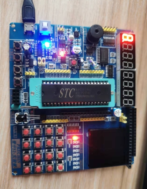
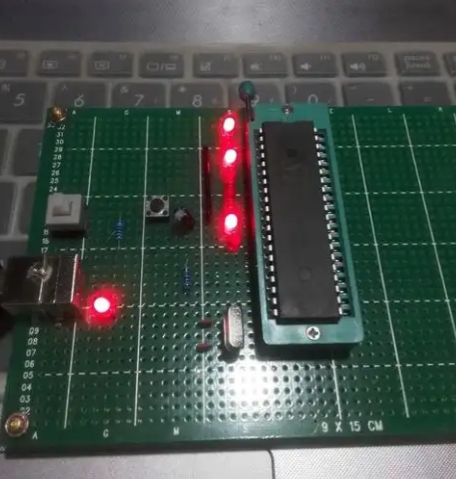
The foundation of any 8051 MCU-based electronic clock lies in its hardware configuration. Understanding each component’s role is crucial for a successful build.
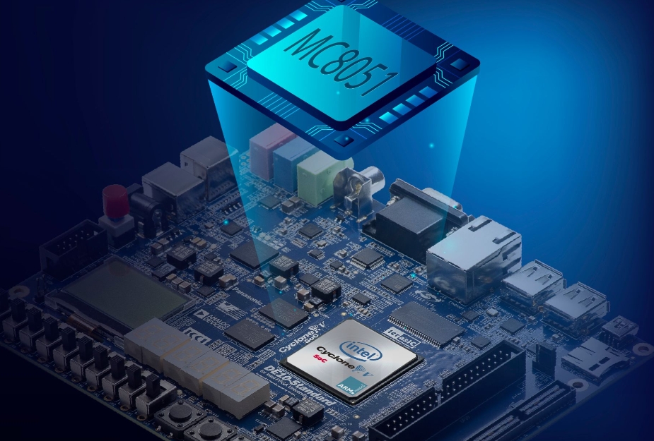
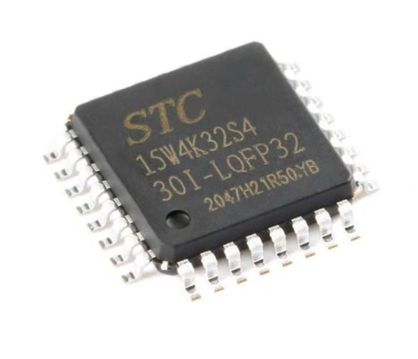
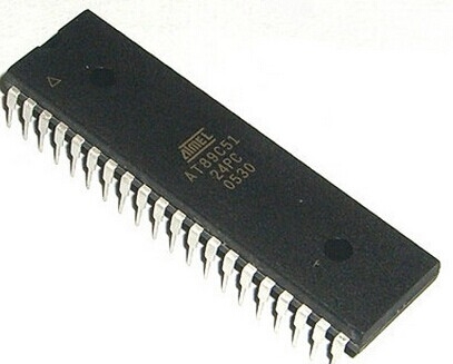
The 8051 Microcontroller is the brain of the operation. While the original Intel 8051 is a historical artifact, modern derivatives like the AT89S52 from Atmel (now Microchip) are widely used. These chips contain all the necessary features: 4KB of Flash memory for program storage, 128 bytes of RAM, 32 I/O pins, two timers, and a serial communication port. For a clock, the timers are particularly important as they allow us to generate precise delays without blocking the CPU.
The Time Base Generation is arguably the most critical part of the circuit. The accuracy of your entire clock depends on it. The 8051 requires an external crystal oscillator connected across pins XTAL1 and XTAL2. For a standard clock, an 11.0592 MHz crystal is often used because it allows for precise baud rate generation for serial communication, though a 12 MHz crystal is also common. This crystal frequency is divided by the microcontroller’s internal circuitry to generate the machine cycle. To achieve one-second intervals, we program one of the internal timers (Timer 0 or Timer 1) to generate periodic interrupts. By loading specific values into the timer’s registers and configuring it in a specific mode (like 16-bit auto-reload mode), we can create an interrupt that triggers exactly 50 times per second (with a 20ms period), which can then be counted up to form one second.
The Display Unit is how the time is presented to the user. The most common and cost-effective method is using a 16x2 Liquid Crystal Display (LCD). This display can show two lines of 16 characters each, perfect for displaying time in an HH:MM:SS format, along with the date. The LCD is interfaced with the 8051 in 4-bit or 8-bit mode, with the data pins connected to one of the ports (e.g., P1) and the control pins (RS, RW, E) connected to other I/O pins. An alternative, more basic display is a 7-segment display multiplexed across several digits. This method is more complex in terms of programming but offers a classic digital clock look and is excellent for learning about multiplexing techniques to drive multiple displays with a limited number of I/O pins.
User Input and Real-Time Clock (RTC) Backup. A simple clock needs buttons to set the time. Typically, three tactile switches are connected to other I/O pins: one for selecting the field to change (hours, minutes, etc.), one for incrementing, and one for decrementing. For a more professional and robust solution, especially one that needs to maintain time during a power loss, integrating a dedicated Real-Time Clock (RTC) chip like the DS1307 is highly recommended. This low-power chip has its own battery backup and communicates with the 8051 via the I2C protocol, providing accurate year, month, date, and time data.
When sourcing these components, especially specific 8051 variants or RTC modules, finding a trustworthy supplier is key. This is where services like ICGOODFIND prove invaluable, as they aggregate information and availability from numerous distributors, saving developers significant time and effort in the component selection phase.
Programming Logic and Firmware Development
With the hardware in place, the next step is to breathe life into the system through software. The program, written in C or Assembly language, is responsible for initializing peripherals, keeping track of time, updating the display, and responding to user input.
Initialization Routines form the first part of the code. This involves setting up the port configurations (input or output), initializing the LCD by sending a series of commands to prepare it for data display, and most importantly, configuring the timer. The timer is set up by writing to two special function registers: TMOD (Timer Mode) and TCON (Timer Control). For instance, we might set Timer 0 to operate in Mode 1 (16-bit non-auto-reload) or Mode 2 (8-bit auto-reload). The initial count value (TH0 and TL0) is calculated based on the crystal frequency to achieve the desired overflow rate (e.g., every 50ms). The Timer Interrupt (IE) register is then configured to enable the timer overflow interrupt.
The Interrupt Service Routine (ISR) is the heart of the timekeeping logic. When the timer overflows, it triggers an interrupt, forcing the CPU to pause its main task and jump to the ISR. Inside this routine: 1. The timer registers are reloaded with the initial count value to maintain consistent timing. 2. A counter variable is incremented. 3. When this counter reaches a specific value (e.g., 20 for a 50ms interrupt equals 1 second), it is reset, and the main “seconds” variable in our timekeeping structure is incremented.
The code then handles the cascading effect of time: when seconds reach 60, they reset to zero and minutes are incremented; when minutes reach 60, they reset and hours are incremented; and so on for days and months.
The Main Program Loop is an infinite loop (while(1)) that handles non-time-critical tasks. * Display Update: It continuously formats the hours, minutes, and seconds into a readable string and sends it to the LCD. * Button Polling: It checks the status of the input buttons. To avoid false triggers from mechanical bouncing, implementing a software debouncing delay of a few tens of milliseconds after detecting a press is essential. When a valid press is detected, flags are set or variables are modified to enter “set mode,” where the user can adjust the time. * RTC Communication (if used): In this case, instead of relying on an internal timer for long-term accuracy,the main loop would periodically read the current time from the DS1307 RTC chip over I2C and then display that value.
Applications and Advanced Enhancements
A basic digital clock is an excellent achievement, but its potential can be greatly expanded with additional features that showcase further capabilities of embedded systems.
Basic Timekeeping Applications are plentiful. A simple 8051 clock can be integrated into home appliances like microwaves and ovens, used as a desktop accessory, or serve as an educational tool in classrooms to teach digital logic and microcontroller programming.
Advanced Feature Integration can transform your basic clock into a sophisticated device. * Alarm Functionality: By comparing the current time with a user-set alarm time stored in variables or EEPROM,the microcontroller can activate a buzzer or an LED at the designated moment. * Temperature Display: Integrating a sensor like the LM35 or DS18B20 allows you to measure ambient temperature.The firmware can read the analog voltage from LM35 using the ADC (if available on an enhanced 8051) or communicate digitally with DS18B20,and then display this data on the LCD alongside the time. * Calendar Functionality: Expanding your timekeeping structure to include day, date, month,and year variables allows you to create a full calendar.This requires implementing logic for different month lengths and leap years,a classic programming challenge. * Serial Communication: You can interface your clock with a PC by using the 8051’s built-in UART.A simple Python script on the computer could then send commands to setthe time or retrieve data logs,making it part of alarger data acquisition system.For complex projects requiring specialized ICs or development boards,turningtoa platform like ICGOODFIND can help you quickly locate themodules you need without scouring multiple supplier websites.
Conclusion
Building an electronic clock with an 8051 microcontroller is far more than just creating atimepiece;it’s ajourney through foundational embedded systems design.It solidifies understandingsof hardware interfacing,the critical natureof precise timer programming,and structured firmware development.From selectingthe right crystal oscillatorto writing efficient interrupt service routinesand integrating user inputs,the project offersa complete hands-on learning experience.The knowledge gainedis directly transferableto more complex applicationsin automation,IoT,and consumer electronics.Furthermore,the project highlights how modern component aggregation platformslike ICGOODFIND empower developersby simplifyingthe partssourcing process.Whether you are astudent,a hobbyist lookingfor apractical project,and engineer prototypinga concept,masteringthe 8051 electronic clock providesa solidand rewarding foundationfor future innovationsin digital design.