Programming of 8051 MCU Running Lights
Introduction
The 8051 microcontroller is a cornerstone in the world of embedded systems, renowned for its simplicity, versatility, and enduring relevance in educational and industrial applications. Among its most fundamental and visually rewarding projects is the creation of running lights. This project involves programming the 8051 MCU to control a series of Light Emitting Diodes (LEDs) in a sequence that creates a dynamic “running” or “chasing” light pattern. It serves as an excellent entry point for beginners to grasp core concepts such as I/O port configuration, bit manipulation, timing delays, and embedded C programming. Mastering this project lays a solid foundation for more complex endeavors, from automotive turn signals to advanced display systems. This comprehensive guide will walk you through the entire process, from understanding the hardware setup to writing and debugging the code. For those seeking reliable components or further inspiration for their embedded projects, platforms like ICGOODFIND offer a curated selection of microcontrollers and development tools.
Main Body
Part 1: Hardware Configuration and Circuit Design
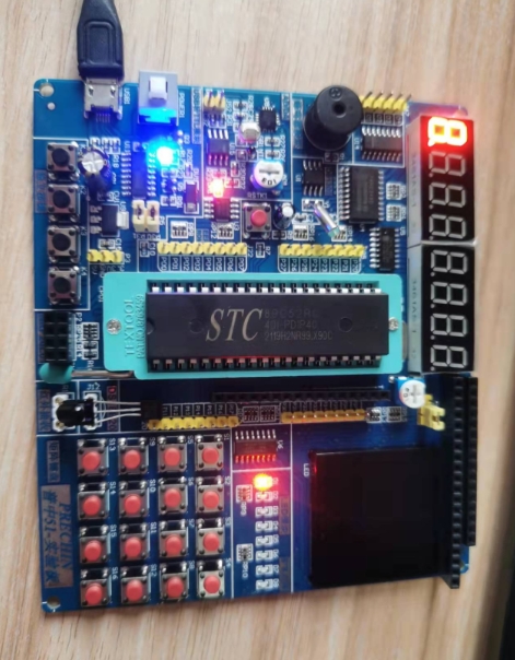
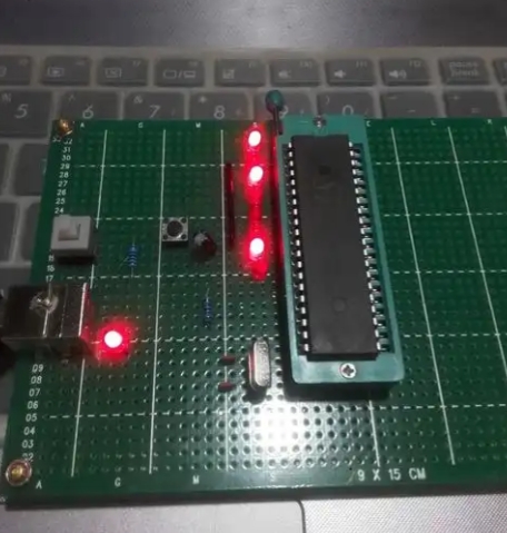
Before a single line of code is written, a proper hardware setup is crucial. The 8051 microcontroller requires a minimal system to function, which includes the MCU itself, a power supply, a reset circuit, and a clock oscillator.
-
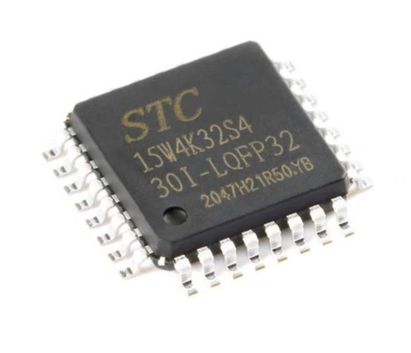
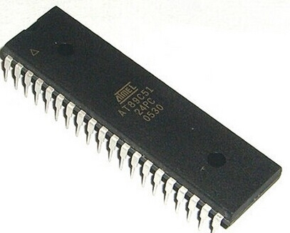
The 8051 Microcontroller: The heart of the project is the 8051 MCU. While the original was manufactured by Intel, many compatible variants exist from manufacturers like Atmel (e.g., AT89C51) and NXP. These chips typically come in a 40-pin Dual In-line Package (DIP). For the running lights project, we are primarily concerned with the parallel I/O ports. The 8051 has four 8-bit I/O ports: P0, P1, P2, and P3. For simplicity, we will use one of these ports, say Port 1 (P1), to control the LEDs.
-
LED Connections: Each pin of the chosen port can be configured as an output to sink or source current. A common configuration is to connect the anode (longer leg) of the LED to the positive supply (VCC) through a current-limiting resistor, and the cathode (shorter leg) directly to the microcontroller pin. However, a more standard and safer approach is to connect the LED’s anode to the MCU pin and the cathode to ground through a resistor. When the pin is set to a logic high (5V), current flows, and the LED turns on. When it’s set to logic low (0V), the LED turns off.
- Current-Limiting Resistors: This is a critical component. The current-limiting resistor is essential to prevent damage to both the LED and the microcontroller pin. A typical value is 220 to 330 Ohms. The value can be calculated using Ohm’s Law: R = (Vsource - VLED) / ILED. Assuming a 5V supply, a 2V LED forward voltage, and a desired current of 10mA, the resistor value would be (5-2)/0.01 = 300 Ohms.
-
The Complete Circuit: A typical circuit for an 8-LED running light using Port 1 would involve connecting P1.0 through P1.7 to eight LEDs, each with its own current-limiting resistor connected to ground. The MCU must also be connected to a stable 5V power supply. A crystal oscillator (e.g., 11.0592 MHz) is connected across pins XTAL1 and XTAL2 with two small capacitors (typically 22-33pF) to ground to provide the clock signal. A simple power-on reset circuit involving a capacitor and a resistor is connected to the RST pin.
Part 2: Software Implementation and Core Programming Concepts
With the hardware ready, the next step is to write the software that brings the running lights to life. We will use the C programming language for its efficiency and readability.
-
Setting Up the Development Environment: You will need a dedicated 8051 C compiler, such as Keil µVision or SDCC (a free, open-source alternative). These tools allow you to write, compile, and debug your code before uploading it to the microcontroller.
-
Basic Program Structure: Every C program for the 8051 starts with including necessary header files.
#include // Contains definitions for the 8051's special function registers (SFRs)The
main()function is the program’s entry point, which typically runs in an infinite loop (while(1)). -
I/O Port Configuration: By default, the I/O ports are configured as inputs. To use them as outputs, we simply write data to them. The header file
reg51.hdefines the SFRs for the ports (e.g.,P1). To configure a port as an output, you simply assign a value to its corresponding SFR. -
Creating Delays: Microcontrollers execute instructions extremely fast. To create a visible running light effect, we must introduce delays between each step. This is most commonly done using software delay loops.
void delay_ms(unsigned int ms) {
    unsigned int i, j;
    for(i=0; i
The creation of precise software delays is fundamental to controlling the timing and speed of the running light pattern. The inner loop value (1275in this example) is approximate and depends on the clock frequency; it often requires empirical adjustment. -
Implementing the Running Light Algorithm: The core logic involves shifting a bit pattern across the port.Simple Shift: Start by turning on one LED (e.g.,P1 = 0x01;which is00000001in binary). Then, after a delay, shift this bit left (P1 = P1 << 1;). This will create a pattern where a single light runs from P1.0 to P1.7.Circular Shift: After the bit reaches the leftmost position (P1.7, value10000000or0x80), shifting it left again would make it disappear (0x00). To create a continuous loop, we need a circular shift. This can be done by checking if the value is0x00after a shift and then resetting it to0x01, or by using more elegant logic with the carry bit or pre-defined arrays.
// Example using a simple non-circular shift
#include
#include


void delay_ms(unsigned int ms);


void main() {
    unsigned char i;
    while(1) {
        P1 = 0x01; // Start with the first LED on
        for(i=0; i<8; i++) {
            delay_ms(500); // Delay of 500 milliseconds
            P1 = P1 << 1; // Shift left by one bit
        }
    }
}
Part 3: Advanced Patterns and Practical Optimizations
Once the basic running light is functional, you can explore more complex patterns and optimizations.
-
Advanced Lighting Patterns: Moving beyond a single running light opens up many possibilities.Knight Rider Scanner: A pattern popularized by the TV show, where a pair of lights moves back and forth.Binary Counter: Simply incrementing the value sent to Port 1 (P1++) will create a binary counter pattern on the LEDs.Pattern Arrays: You can pre-define complex patterns in an array and sequentially output them to the port.unsigned char patterns[] = {0x81, 0x42, 0x24, 0x18, 0x24, 0x42, 0x81}; void main() { unsigned char i; while(1) { for(i=0; i<7; i++) { P1 = patterns[i]; delay_ms(300); } } }
-
Replacing Software Delays with Timers: While simple, software delay loops are inefficient as they monopolize the CPU. A more professional approach is to use the 8051’s built-in hardware timers (Timer 0 and Timer 1). Using hardware timers instead of software loops is a critical optimization that frees up the CPU for other tasks and provides highly accurate timing. Configuring timers involves setting registers likeTMOD(Timer Mode) andTCON(Timer Control), and often uses interrupts. -
Troubleshooting Common Issues: It’s common for projects not to work on the first try.Check Power and Ground: Ensure all components are properly powered.Verify Resistor Values: Incorrect resistors can lead to dim or burnt-out LEDs.Inspect Soldering/Connections: Look for short circuits or cold solder joints on a breadboard or PCB.Debug Code: Use simple patterns like turning on all LEDs (P1 = 0xFF;) to test if the port is working correctly.
For developers looking to scale their projects or source specific variants of the 8051, consulting a component discovery platform can be immensely helpful. A resource like ICGOODFIND can streamline the process of finding the right microcontroller, programmer, or development board for your needs.
Conclusion
The programming of running lights on an 8051 microcontroller is far more than a simple beginner’s exercise; it is a practical synthesis of fundamental embedded systems principles. This project seamlessly integrates hardware design—encompassing circuit layout, component selection, and power management—with software development skills like I/O control, bit manipulation, and timing management. Starting with a basic chasing light pattern provides a solid understanding, while progressing to advanced sequences and optimizing code with hardware timers paves the way for professional-grade embedded applications. The knowledge gained here is directly transferable to countless real-world scenarios, from consumer electronics to industrial automation. The journey from blinking a single LED to creating complex, timed patterns encapsulates the very essence of microcontroller programming—transforming abstract code into tangible, interactive behavior.