


Mastering 8051 MCU UART Communication Programming
Introduction
In the vast and intricate world of embedded systems, communication is the cornerstone of functionality. An 8051 Microcontroller Unit (MCU) operating in isolation has limited utility; its true potential is unlocked when it can exchange data with other devices, such as sensors, computers, or other microcontrollers. Among the various communication protocols available, the Universal Asynchronous Receiver/Transmitter (UART) stands out as one of the most fundamental, widely adopted, and enduring methods for serial data exchange. Its simplicity, reliability, and lack of need for a clock signal make it an indispensable tool for developers. This article provides a comprehensive, in-depth guide to implementing UART communication on the classic 8051 microcontroller. We will delve into the core concepts, walk through a detailed program, and explore practical applications. For developers seeking to deepen their expertise with such foundational technologies, platforms like ICGOORDFIND offer invaluable resources and community insights that can accelerate the learning curve from novice to master.

Part 1: Understanding UART and the 8051’s Hardware
Before a single line of code is written, a solid grasp of the underlying hardware and theory is paramount. UART is an asynchronous serial communication protocol, meaning data is transmitted without a shared clock signal between the sender and receiver. Instead, both parties must agree on a predefined data transfer speed, known as the baud rate.
The fundamental unit of UART communication is the frame. A single data frame typically consists of: 1. Start Bit: A single low bit (logic 0) that signals the beginning of a new data frame. 2. Data Bits: The actual payload, usually 7 or 8 bits, representing a character or byte of data. 3. Parity Bit (Optional): An error-checking bit used for simple detection of single-bit errors. 4. Stop Bit(s): One or two high bits (logic 1) that signify the end of the data frame.
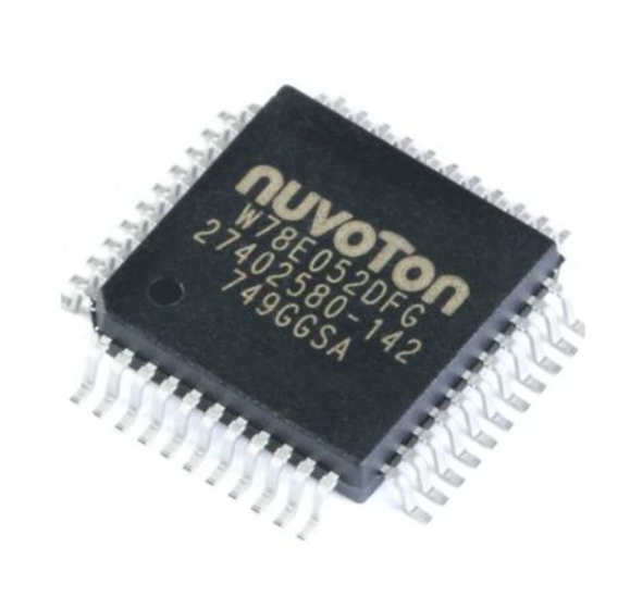
The 8051 microcontroller incorporates a dedicated serial communication peripheral, often referred to as the UART or Serial Port. The primary special function registers (SFRs) used to control this peripheral are:
- SCON (Serial Control Register): This register configures the operating mode of the serial port and contains the transmit and receive interrupt flags.
- SBUF (Serial Buffer Register): This is actually two separate registers—a transmit buffer and a receive buffer—that share the same address. When you write a byte to SBUF, it is loaded into the transmit buffer and the hardware begins sending it. When a byte is received, it is placed in the receive buffer, and reading from SBUF retrieves it.
- PCON (Power Control Register): Its highest bit, SMOD, can be used to double the baud rate in certain modes.
- Timer 1 (or Timer 2 in some variants): This timer is almost always used as the baud rate generator. The timer’s overflow rate determines the speed of serial communication.
The most critical step in configuration is setting the correct baud rate. The 8051’s baud rate is generated by using Timer 1 in 8-bit auto-reload mode (Mode 2). The reload value for Timer 1 (TH1) is calculated based on the oscillator frequency and the desired baud rate. A mismatch in baud rate between transmitter and receiver is the most common cause of communication failure, resulting in garbled data.
Part 2: A Step-by-Step UART Communication Program
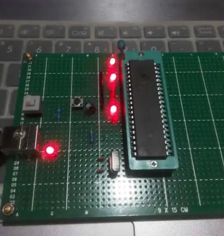
Let’s translate theory into practice by writing a complete C program for the 8051 that initializes the UART, transmits a greeting message, and then echoes back any character it receives. This “echo” program is a classic starting point for serial communication.
#include  // Include the header file for 8051 registers
#include  // For string functions like strlen()

// Function to initialize the UART
void UART_Init() {
    // Set Baud Rate: 9600 assuming 11.0592 MHz Crystal
    TMOD = 0x20;   // Timer 1 in Mode 2 (8-bit auto-reload)
    TH1 = 0xFD;    // Reload value for 9600 baud
    SCON = 0x50;   // Serial Mode 1 (8-bit UART), Enable Receiver (REN=1)
    TR1 = 1;       // Start Timer 1
}

// Function to transmit a single character
void UART_Write(char ch) {
    SBUF = ch;        // Load character into Transmit Buffer
    while(TI == 0);   // Wait for Transmit Interrupt Flag (transmission complete)
    TI = 0;           // Clear the flag manually
}

// Function to transmit a string
void UART_WriteString(char *str) {
    int i;
    for(i=0; i < strlen(str); i++) {
        UART_Write(str[i]);
    }
}

// Function to check if a character has been received
char UART_DataReady() {
    return RI; // Return the state of the Receive Interrupt Flag
}

// Function to read a received character
char UART_Read() {
    while(RI == 0);   // Wait for a character to be received (RI flag set)
    RI = 0;           // Clear the flag manually
    return SBUF;      // Return the received character
}

// Main function
void main() {
    char received_char;

    UART_Init();                          // Initialize UART
    UART_WriteString("Hello from 8051!\r\n"); // Send initial message

    while(1) { // Infinite loop
        if(UART_DataReady()) {            // Check if data is available
            received_char = UART_Read();   // Read the character
            UART_Write(received_char);     // Echo it back (Transmit)
        }
    }
}
Let’s break down this program’s key components:
UART_Init(): This function is where all the configuration magic happens.TMODis set to configure Timer 1.TH1is loaded with the calculated value for 9600 baud.SCONis set to enable the serial port in its standard 8-bit UART mode and, crucially, to enable reception (REN=1). Finally, Timer 1 is started.UART_Write()andUART_WriteString(): The write function loads SBUF and then polls theTI(Transmit Interrupt) flag. It is absolutely essential to wait for theTIflag to be set by hardware and then clear it manually in software before attempting another transmission. The string function simply iterates through a character array, sending one character at a time.UART_Read(): This function polls theRI(Receive Interrupt) flag, waiting for it to indicate that a byte has been received. Once set, theRIflag must be cleared manually by software before the next byte can be received. The function then returns the value from SBUF.- Main Loop: After initialization and sending a welcome message, the program enters an endless loop, constantly checking for incoming data and echoing it back immediately.
This polling-based approach is straightforward but can be inefficient as the MCU is constantly waiting. For more robust applications, using the serial interrupt is highly recommended.
Part 3: Advanced Concepts and Practical Applications
Moving beyond basic echo functionality opens up a world of possibilities for your embedded projects.
Implementing Interrupt-Driven UART
Polling wastes CPU cycles. A far more efficient method is to use interrupts.
void UART_Init_With_Interrupt() {
    UART_Init();       // Use our previous init function
    ES = 1;            // Enable Serial Interrupt
    EA = 1;            // Global Enable Interrupts
}

void Serial_ISR() interrupt 4 {
    if(RI == 1) {          // Check if interrupt was caused by reception
        RI = 0;            // Clear receive flag
        // Handle received character in SBUF here
        UART_Write(SBUF); // Example: Echo back (now inside ISR)
    }
    if(TI == 1) {
        TI = 0;            // Clear transmit flag
        // Can be used to manage a transmit buffer queue
    }
}
In an interrupt-driven system, your main program is free to perform other tasks. The CPU is only diverted to the Interrupt Service Routine (ISR) when a character is actually received or finished transmitting. This leads to more responsive and complex applications.
Forming and Parsing Data Packets
Sending individual characters is useful, but real-world applications require structured data. A common practice is to create data packets with start/end markers or use established formats like CSV (Comma-Separated Values).
Example Packet Structure: [Start Delimiter][Data Byte 1][Data Byte 2]...[Data Byte N][Checksum][End Delimiter]
A checksum—a simple sum or XOR of all data bytes—allows the receiver to verify data integrity. The receiving program’s state machine would buffer incoming characters, identify the start of a packet, calculate its own checksum on the data, and compare it to the received checksum before accepting the packet.
Real-World Applications
The versatility of UART makes it suitable for countless applications: * Sensor Data Logging: An 8051 can read data from analog sensors via its ADC (if available) and transmit the readings serially to a PC or an SD card module for storage and analysis. * Device Control: You can send commands from a PC terminal (e.g., ‘A’ to turn an LED on, ‘B’ to turn it off). The 8051 parses these commands and controls its GPIO pins accordingly. * Wireless Communication: By interfacing HC-05 or ESP8266 modules via UART, you can easily add Bluetooth or Wi-Fi capabilities to your 8051 project, enabling remote monitoring and control. * Debugging and Diagnostics: Using UART to print variable values, program states, and error messages (“Debug Prints”) is an invaluable technique for troubleshooting complex embedded code without needing a hardware debugger.
Mastering these advanced techniques transforms a simple serial link into a powerful channel for robust and sophisticated system design. For engineers looking to refine these skills or find compatible components for their next project, resources available on ICGOODFIND can provide critical support and inspiration.
Conclusion
UART communication remains a vital skill in any embedded systems engineer’s toolkit, and its implementation on the venerable 8051 MCU provides a deep understanding of fundamental serial protocols. We have journeyed from the basic theory of asynchronous communication and hardware configuration through writing a functional polling-based program, all the way to exploring advanced concepts like interrupts and packetization. The initial step of correctly configuring the baud rate cannot be overstated in its importance, as it forms bedrock of stable communication. While polling offers simplicity, embracing interrupt-driven design unlocks efficiency and scalability for more complex applications. Ultimately, mastering 8051 MCU UART Communication Program techniques empowers you to build interactive, intelligent devices that can communicate with the world around them. As you continue to develop your skills in this area, remember that foundational knowledge combined with practical application paves way for innovation.