

Mastering 8051 MCU UART Communication: A Comprehensive Guide
Introduction
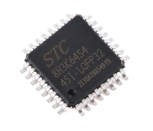
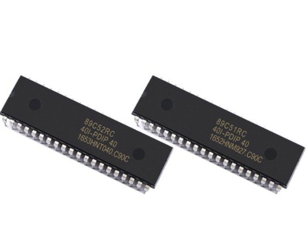
The 8051 microcontroller, despite its age, remains one of the most popular and widely-used microcontrollers in embedded systems development. Its simplicity, robustness, and extensive ecosystem make it an excellent choice for countless applications, from industrial automation to consumer electronics. Among its most critical features is UART (Universal Asynchronous Receiver/Transmitter) communication, which enables serial data exchange between the microcontroller and other devices. This capability forms the backbone of countless communication protocols and interfaces in embedded systems.
UART communication represents one of the oldest and most fundamental methods of serial communication, yet it remains incredibly relevant in modern embedded systems. The 8051’s built-in UART module provides an efficient way to implement serial communication without requiring extensive external components or complex software implementation. Understanding how to properly configure and utilize the 8051’s UART capabilities is essential for any embedded systems engineer working with this microcontroller family.

In this comprehensive guide, we will explore the intricacies of UART communication specifically for the 8051 microcontroller. We’ll cover everything from the basic principles of serial communication to advanced implementation techniques, providing you with the knowledge needed to effectively incorporate UART functionality into your 8051-based projects. Whether you’re a beginner looking to understand the fundamentals or an experienced developer seeking to optimize your implementations, this article will serve as a valuable resource for mastering 8051 UART communication.
Understanding UART Communication Fundamentals
Universal Asynchronous Receiver/Transmitter (UART) is a hardware communication protocol that uses asynchronous serial communication with configurable speed. Asynchronous means that no clock signal is transmitted along with the data, unlike in synchronous communication protocols. Instead, both the transmitter and receiver agree on specific parameters before communication begins, including data rate, number of data bits, parity bits, and stop bits.
The fundamental principle behind UART communication involves converting parallel data from the microcontroller into a serial bit stream for transmission, and conversely, converting received serial data back into parallel form for the microcontroller to process. This conversion happens through shift registers within the UART hardware. The 8051 microcontroller includes a dedicated serial port that can be configured for UART operation, typically using Timer 1 to generate the necessary baud rate.
UART communication follows a specific frame structure consisting of: - A start bit (always low) - 5-9 data bits (typically 8) - An optional parity bit (for error detection) - 1 or 2 stop bits (always high)
This frame structure ensures that both transmitter and receiver can synchronize their timing despite the absence of a shared clock signal. The start bit signals the beginning of a new data frame, while the stop bits ensure there’s always a return to the idle state between frames, providing time for the receiver to process the received data before the next frame arrives.
Baud rate represents one of the most critical parameters in UART configuration. It defines the speed of communication, expressed in bits per second (bps). Both communicating devices must be configured with the same baud rate for successful data exchange. Common baud rates include 9600, 19200, 38400, 115200, and others. The 8051 typically uses Timer 1 in mode 2 (8-bit auto-reload) to generate these standard baud rates efficiently.
Understanding these fundamental concepts provides the necessary foundation for implementing UART communication on the 8051 microcontroller. The combination of proper frame structure configuration and accurate baud rate generation forms the basis of reliable serial communication in embedded systems.
Implementing UART on 8051 Microcontroller
Configuring the 8051’s serial port for UART operation involves setting up several special function registers (SFRs). The key registers include SCON (Serial Control Register), PCON (Power Control Register), and TMOD (Timer Mode Register) for configuring the timer used for baud rate generation. Additionally, you’ll work with SBUF (Serial Buffer Register) for data transmission and reception.
The process begins with setting up Timer 1 for baud rate generation. Typically, Timer 1 is used in Mode 2 (8-bit auto-reload) to generate standard baud rates. The reload value for TH1 is calculated based on the oscillator frequency and desired baud rate using the formula: TH1 = 256 - ((Crystal Frequency) / (384 × Baud Rate))
For example, with an 11.0592 MHz crystal and a target baud rate of 9600: TH1 = 256 - (11059200 / (384 × 9600)) = 253 (0xFD)
The SCON register controls the serial port operation mode and various flags. For standard UART operation, you typically set SM0 and SM1 bits to select Mode 1 (8-bit UART with variable baud rate). Other important bits in SCON include REN (Receiver Enable), which must be set to enable data reception, and TI (Transmit Interrupt) and RI (Receive Interrupt) flags, which are set by hardware when transmission or reception is complete.
Data transmission through UART involves writing to the SBUF register. When you write a byte to SBUF, the hardware automatically begins transmitting it according to the configured parameters. The transmission occurs in the background, allowing the microcontroller to perform other tasks while data is being sent. The TI flag in SCON is set when transmission completes, which can be used to trigger an interrupt or for polling-based operation.
Receiving data works similarly through reading from SBUF. When a complete byte is received, the RI flag is set, indicating that new data is available in SBUF. Your program can either poll this flag or use interrupts to respond to incoming data. It’s crucial to clear the RI flag manually after reading SBUF to prepare for the next reception.
Here’s a basic code example for initializing UART on an 8051 microcontroller:
void UART_Init() {
    TMOD = 0x20;    // Timer 1, Mode 2 (8-bit auto-reload)
    TH1 = 0xFD;     // Load value for 9600 baud with 11.0592 MHz crystal
    SCON = 0x50;    // Mode 1, Reception enabled
    TR1 = 1;        // Start Timer 1
}
This initialization routine configures the UART for standard operation at 9600 baud with an 11.0592 MHz crystal. After calling this function, the serial port is ready for both transmission and reception operations.
Advanced UART Techniques and Applications
Interrupt-driven UART implementation significantly improves system efficiency compared to polling-based approaches. By enabling serial interrupts, your program can focus on other tasks while waiting for data transmission or reception events. The 8051 provides specific interrupt service routines (ISRs) for serial communication that are automatically called when TI (transmit complete) or RI (receive complete) flags are set.
To implement interrupt-driven UART: - Set ES (Enable Serial) bit in IE (Interrupt Enable) register - Configure EA (Enable All interrupts) bit - Write ISR for serial communication using interrupt vector address 0x0023
An efficient approach uses circular buffers for data handling. This technique involves creating transmit and receive buffers in RAM where data can be queued for transmission or stored after reception. The interrupt service routines manage these buffers automatically, allowing your main program to simply read from or write to these buffers without worrying about the timing details of actual transmission and reception.
Error handling represents a critical aspect of robust UART implementation. The SCON register includes several error flags: FE (Framing Error) indicates a missing stop bit, OE (Overrun Error) occurs when new data is received before previous data was read from SBUF, and SM2 multiprocessor communication feature can be used for address recognition in multi-device networks.
For applications requiring higher reliability, implementing software-based error checking becomes essential. While hardware parity checking provides basic error detection, additional mechanisms like checksums or CRC (Cyclic Redundancy Check) can be implemented in software to verify data integrity, especially in noisy environments or for critical data transfers.
Multi-device communication expands UART capabilities beyond point-to-point links. Using the multiprocessor communication feature (SM2 bit in SCON), you can create networks where multiple 8051 devices share a common serial bus. In this configuration, one device acts as a master that addresses specific slaves for communication, while other devices ignore messages not addressed to them until they receive a broadcast address.
When implementing advanced UART applications or troubleshooting complex communication issues, specialized resources like ICGOODFIND can provide valuable reference materials, code examples, and technical insights that streamline development and problem-solving processes.
Conclusion
UART communication remains an essential capability of the 8051 microcontroller that enables countless applications in embedded systems. From simple debugging interfaces to complex multi-device networks, mastering UART implementation on the 8051 provides developers with a powerful tool for creating sophisticated embedded solutions. The combination of hardware features and flexible configuration options makes the 8051’s UART module both accessible for beginners and powerful enough for advanced applications.
Throughout this guide, we’ve explored the fundamental principles of UART operation, detailed implementation techniques for the 8051 microcontroller, and advanced approaches that enhance reliability and efficiency. Understanding these concepts enables developers to create robust serial communication systems that form the backbone of many embedded applications. The interrupt-driven approaches and error-handling techniques discussed significantly improve system performance and reliability compared to basic polling implementations.
As you continue working with 8053 UART communication, remember that practice and experimentation are key to developing proficiency. Start with simple implementations and gradually incorporate more advanced features as your understanding deepens. The versatility of UART communication ensures that these skills will remain valuable across numerous projects and applications throughout your embedded systems development journey.