


Mastering 8051 MCU Assembly Language: A Comprehensive Guide for Embedded Systems Development
Introduction
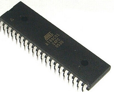
The 8051 microcontroller, originally developed by Intel in 1980, remains one of the most influential and widely-used microcontroller architectures in the embedded systems world. Despite the proliferation of more modern microcontroller families, the 8051 continues to thrive in numerous applications ranging from automotive systems and industrial controls to consumer electronics and IoT devices. At the heart of the 8051’s enduring popularity lies its elegant instruction set and the raw power of assembly language programming. While high-level languages like C have become more prevalent in embedded development, assembly language provides unparalleled control over hardware resources and execution timing, making it essential for time-critical applications and resource-constrained environments. Understanding 8051 assembly language is not just an academic exercise—it’s a practical skill that enables developers to write highly efficient code, optimize performance, and deeply comprehend how microcontrollers interact with their environment. This comprehensive guide explores the fundamentals, advanced techniques, and real-world applications of 8051 assembly programming, providing both newcomers and experienced developers with valuable insights into this powerful development approach.
The Foundation of 8051 Assembly Programming
Understanding the 8051 Architecture
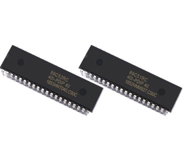
To effectively program in 8051 assembly language, developers must first understand the underlying hardware architecture. The 8051 microcontroller features a Harvard architecture with separate memory spaces for program and data, which distinguishes it from von Neumann architectures used in general-purpose processors. The 8051’s memory organization is divided into three distinct areas: program memory (ROM), internal data memory (RAM), and external data memory. The internal RAM is particularly important for assembly programmers as it contains the register banks, bit-addressable memory, and general-purpose storage areas that are directly accessible through specialized instructions.
The 8051’s central processing unit operates on an 8-bit architecture, meaning it processes data in 8-bit chunks. However, it’s crucial to understand that the data bus is 8 bits wide while the address bus is 16 bits wide, enabling the microcontroller to address up to 64KB of program memory and 64KB of data memory. The CPU contains several key components including the Arithmetic Logic Unit (ALU), accumulator (A register), B register, Program Counter (PC), Data Pointer (DPTR), and Stack Pointer (SP). Each of these elements plays a critical role in program execution and must be thoroughly understood by assembly language programmers.
Another fundamental aspect of the 8051 architecture is its rich set of peripherals integrated onto the chip. These include four 8-bit I/O ports, two 16-bit timer/counters, a full-duplex serial communication port (UART), and an interrupt controller with five interrupt sources. Mastering how to control these peripherals through Special Function Registers (SFRs) is essential for effective assembly programming. SFRs are mapped into specific memory locations above 80H and provide direct control over all the microcontroller’s features, from configuring timer modes to setting serial communication parameters.
Essential Assembly Language Syntax and Directives
8051 assembly language follows a specific syntax structure that programmers must adhere to for successful compilation. Each line of assembly code typically consists of four fields: label, mnemonic, operand, and comment. The label field (optional) provides a symbolic name for a memory location, the mnemonic field contains the actual instruction, the operand field specifies the data or address the instruction operates on, and the comment field (optional) allows programmers to document their code. Proper use of labels and comments significantly enhances code readability and maintainability, especially in complex projects.
Assembly language programs rely heavily on assembler directives, which are instructions to the assembler rather than the microcontroller itself. These directives perform various functions such as defining constants, reserving memory space, and including external files. Some of the most important directives in 8051 assembly include ORG (set program origin), EQU (define a constant), DB (define byte), DW (define word), DS (define storage), and BIT (define a bit address). Understanding how to use these directives effectively separates novice programmers from experts, as they enable better organization of code and data in memory.
The operand field in 8051 instructions can utilize several addressing modes, each with specific use cases and limitations. The 8051 supports seven addressing modes: immediate, direct, register, register indirect, indexed, relative, and absolute. Immediate addressing uses constant data included in the instruction itself. Direct addressing accesses memory locations directly using their 8-bit addresses. Register addressing uses one of the eight general-purpose registers (R0-R7). Register indirect addressing uses a register as a pointer to memory. Indexed addressing combines the base address in DPTR or PC with an offset in the accumulator. Relative addressing calculates jump destinations relative to the current program counter. Absolute addressing specifies exact jump addresses within the current 2KB page. Mastering when and how to use each addressing mode is crucial for writing efficient assembly code.
Core Instruction Set Categories
The 8051 instruction set can be divided into several functional categories based on their operations. Data transfer instructions enable moving data between different memory spaces and registers. This category includes MOV instructions for general data transfer, MOVX instructions for accessing external data memory, MOVC instructions for reading from program memory, PUSH and POP instructions for stack operations, and XCH instructions for exchanging data between registers and memory. Understanding the limitations of these instructions—such as which addressing modes work with which instructions—is vital for effective programming.
Arithmetic instructions perform mathematical operations on data in registers and memory. The 8051 supports addition (ADD, ADDC), subtraction (SUBB), multiplication (MUL), division (DIV), increment (INC), decrement (DEC), and decimal adjustment (DA A) instructions. It’s important to note that many arithmetic operations use the accumulator as an implicit operand and affect various flags in the Program Status Word (PSW). The PSW contains critical status flags such as Carry (CY), Auxiliary Carry (AC), Overflow (OV), and Parity (P) that must be monitored during arithmetic operations to ensure correct results.
Logical instructions perform bitwise operations on data including AND, OR, XOR, clear (CLR), complement (CPL), and rotate (RL, RLC, RR, RRC) operations. These instructions are particularly useful for manipulating individual bits in I/O ports and control registers. Bit manipulation capabilities represent one of the 8051’s most powerful features, with specific instructions for setting (SETB), clearing (CLR), complementing (CPL), jumping based on bit conditions (JB, JNB, JBC), and moving bits between the carry flag and bit-addressable memory locations.
Program control instructions manage program flow through various jump and call operations. This category includes unconditional jumps (SJMP, LJMP, JMP), conditional jumps (JZ, JNZ, CJNE, DJNZ), subroutine calls (ACALL, LCALL) and returns (RET), interrupt returns (RETI), and no operation (NOP). Understanding the range limitations of different jump instructions is crucial—short jumps (SJMP) have a limited range of -128 to +127 bytes from the next instruction, while long jumps (LJMP) can access any location in the 64KB program memory space.
Advanced Programming Techniques and Optimization
Efficient Memory Management Strategies
Memory optimization is critical in 8051 assembly programming due to the limited resources available in most implementations. The 8051 architecture provides only 128 bytes of internal RAM (256 bytes in enhanced versions), which must be shared between register banks, bit-addressable space, general-purpose variables, and the stack. Strategic allocation of variables across different memory regions can significantly impact both performance and functionality. The lower 32 bytes of internal RAM contain four register banks with eight registers each; selecting the appropriate register bank for different parts of your program can minimize context saving overhead during interrupts.
The stack in 8051 systems grows upward from a location determined by the Stack Pointer (SP) register. Since internal RAM is limited, careful stack management prevents memory corruption from stack overflow. Assembly programmers must estimate worst-case stack usage by considering maximum interrupt nesting levels, subroutine call depths, and temporary variable storage requirements. Placing the stack at an appropriate location—typically at the top of internal RAM—helps prevent collisions between stack operations and variable storage.
External memory interfacing extends the capabilities of 8051 systems beyond their internal limitations. When working with external data memory or additional program memory, programmers must understand how to use MOVX instructions with either DPTR or R0/R1 registers for addressing. Efficient use of paging techniques becomes essential when dealing with more than 256 bytes of external data memory since R0/R1 can only address that much directly. For larger memories, developers implement bank switching schemes or use DPTR for full 16-bit addressing at the cost of additional instruction cycles.
Interrupt Handling and Real-Time Operations
Interrupts are fundamental to responsive embedded systems, allowing microcontrollers to react immediately to external events or internal conditions without continuous polling. The 8051 architecture supports five interrupt sources: two external interrupts (INT0 and INT1), two timer interrupts (TF0 and TF1), and one serial port interrupt (RI/TI). Each interrupt has a fixed priority level and a dedicated vector address where execution jumps when the interrupt occurs. Assembly programmers must carefully manage interrupt enabling through the Interrupt Enable (IE) register and configure interrupt priority using the Interrupt Priority (IP) register when necessary.
Writing efficient interrupt service routines (ISRs) in assembly requires adherence to several best practices. ISRs should preserve all modified registers by pushing them onto the stack upon entry and popping them before returning. Since ISRs should execute as quickly as possible to maintain system responsiveness, time-critical operations should be kept minimal within interrupts—often just setting flags or capturing data—with main program loops handling less urgent processing based on those flags. The RETI instruction used to return from interrupts not only restores program flow but also re-enables interrupt recognition at the same priority level.
Real-time operations often require precise timing control achieved through careful management of the 8051’s timer/counter peripherals. The two 16-bit timer/counters can be configured in different modes including 13-bit timer mode, 16-bit timer mode, 8-bit auto-reload mode, and counter mode. Assembly programmers can achieve highly accurate timing by calculating initial timer values based on system clock frequency and desired intervals. For periodic events using mode 2 auto-reload or implementing software reload routines for other modes ensures consistent timing without cumulative errors.
Peripheral Interface Programming
The 8051’s integrated peripherals provide powerful capabilities that assembly programmers can leverage for various applications. The four parallel I/O ports each have distinct characteristics—Port 0 requires external pull-up resistors when used for general I/O but serves as multiplexed address/data bus when accessing external memory; Ports 1-3 have internal pull-ups but may have alternate functions that need configuration; Port 2 serves as high-order address bus when using external program or data memory beyond 256 bytes.
Serial communication programming enables interaction with other devices using standard protocols like UART RS-232. The 8051’s serial port can operate in four distinct modes with different baud rates and data formats controlled through SCON register settings Mode selection depends on application requirements whether simple asynchronous communication synchronous communication or multi-processor systems Baud rate generation typically utilizes Timer 1 operating in auto-reload mode though Timer 2 offers additional options in enhanced variants Assembly code must properly initialize configure monitor status bits handle transmission reception through SBUF register
Analog-to-digital conversion represents another common requirement even though standard doesn’t include ADC peripheral Many implementations incorporate ADCs either as integrated features or external components connected through parallel serial interfaces Assembly programs interface with these converters by generating appropriate control signals managing conversion timing reading result data Proper signal conditioning sampling techniques essential obtaining accurate measurements particularly noisy embedded environments
Practical Applications Development Tools
Development Toolchain Setup
Modern development environments have significantly streamlined process creating testing debugging programs Traditional approaches required hardware emulators incircuit simulators contemporary solutions often incorporate software simulators integrated development environments providing comprehensive toolchains single package Popular options include Keil µVision IAR Embedded Workbench Silicon Labs IDE SDCC open-source compiler assembler Each offers unique features trade-offs regarding cost functionality support
The assembly programming workflow typically involves several stages starting with writing source code using text editor followed by assembling process converts human-readable instructions machine code executable microcontroller Assemblers generate object files potentially multiple modules subsequently processed linker combines them single executable format typically HEX BIN suitable programming microcontroller Many toolchains include librarians managing library archives locators assigning final addresses memory segments simulators debugging without physical hardware
Debugging represents critical aspect development process particularly challenging environment where direct observation internal states impossible Software simulators allow stepping through code inspecting modifying register memory contents setting breakpoints watchpoints Hardware debugging requires additional interfaces like traditional emulators modern JTAG SWD interfaces providing real-time insight microcontroller operation Mixed approaches combining software simulation targeted hardware testing often yield best results balancing efficiency thoroughness
Real-World Application Examples
Digital thermometer implementation demonstrates practical application combining multiple concepts peripheral interfacing data processing display control Typical design might incorporate temperature sensor like LM35 analog output connected ADC microcontroller processes digitized values applies calibration converts appropriate display format drives seven-segment LCD display output Assembly implementation would handle precise timing requirements ADC readouts mathematical conversions mapping binary values readable formats multiplexing displays necessary all while maintaining responsiveness potential user inputs
Stepper motor controller represents another common application leveraging precise timing capabilities assembly programming Stepper motors require specific sequence signals applied coils rotate predefined increments potentially offering precise positioning without feedback systems Assembly program would generate appropriate pulse sequences correct timing accelerate decelerate motors smoothly prevent missed steps calculate required step counts target positions potentially implement microstepping techniques finer resolution Interface might include input controls setting target positions feedback mechanisms limit switches
Security system implementation showcases bit-manipulation capabilities handling multiple input sources controlling various outputs Such system might monitor several sensors door windows motion detect specific patterns indicating potential security breaches activate appropriate responses alarms notifications Assembly strength becomes evident handling multiple binary inputs efficiently using bit-oriented operations minimizing code size execution time while maintaining responsive monitoring all sensors simultaneously Program would likely incorporate debouncing techniques contact sensors filtering false triggers maintaining system state across power interruptions possible RTC integration timestamp events
Best Practices Code Optimization
Writing efficient maintainable requires adherence established best practices beginning consistent coding style comprehensive documentation Meaningful labels variable names liberal comments significantly enhance readability particularly returning code after extended periods Modular design separating functionality discrete subroutines promotes reusability simplifies testing debugging Structured approaches implementing common programming constructs loops conditionals improve clarity reduce errors compared spaghetti code common early assembly programming
Performance optimization focuses primarily reducing execution time code size often conflicting objectives Common techniques include replacing slow operations faster equivalents using logical operations instead arithmetic when possible minimizing memory accesses reusing register values loop unrolling reducing overhead trade-off increased code size Algorithm selection plays crucial role efficient implementations well-chosen algorithm often outperforms highly optimized poor algorithm Selection appropriate data structures access patterns significantly impacts performance particularly dealing large datasets external memory
Power optimization becomes increasingly important battery-powered applications where energy consumption critical concern Assembly programmers can implement various techniques minimize power usage including putting microcontroller sleep modes during idle periods minimizing active computation time reducing clock frequencies possible careful peripheral management disabling unused components Modern variants offer multiple power-saving modes each trading responsiveness power consumption Understanding wake-up sources timing requirements essential implementing effective power management strategies assembly level
Conclusion
Throughout this comprehensive exploration programming we’ve examined fundamental concepts advanced techniques practical applications underpinning successful embedded development Despite proliferation higher-level languages like remains relevant powerful approach particularly resource-constrained time-sensitive applications Deep understanding architecture instruction set enables developers write highly optimized code fully leverage microcontroller capabilities impossible through abstractions higher-level languages provides unparalleled visibility control execution flow resource usage
The journey mastering begins solid foundation architecture progresses through increasingly sophisticated programming concepts real-world implementations Starting simple programs blinking LEDs reading switches gradually building complex systems integrating multiple peripherals implementing sophisticated algorithms provides structured approach developing proficiency Modern development tools simulators debuggers significantly reduce learning curve allowing experimentation observation without risk damaging hardware Online resources communities like provide valuable support knowledge sharing accelerating mastery this powerful programming approach represents excellent platform learning principles applicable wider range microcontroller architectures providing balance complexity capability ideal educational professional contexts As embedded systems continue proliferate across industries from automotive medical IoT applications skills developed through programming remain valuable assets any embedded systems developer toolkit offering level control efficiency simply unattainable through other means represents specialized skill set continues delivering exceptional value performance-critical applications where every clock cycle matters every byte memory precious