Mastering Motor Control: A Deep Dive into the 8051 MCU-Controlled DC Motor
Introduction
In the vast and intricate world of embedded systems and automation, the control of physical motion stands as a fundamental pillar. From the precise positioning in a 3D printer to the simple rotation of a smart home appliance’s fan, the ability to command movement is paramount. At the heart of countless such applications lies a powerful and enduring duo: the DC motor and the microcontroller. While modern 32-bit MCUs offer immense power, the classic 8051 microcontroller remains a cornerstone for understanding and implementing core electronic control principles. Its straightforward architecture and enduring relevance make it an ideal educational and practical platform. This article provides a comprehensive exploration of implementing 8051 MCU-controlled DC motor systems. We will dissect the core components, delve into the programming logic, and examine real-world applications, demonstrating why this combination is a critical skill for engineers and hobbyists alike. For those seeking reliable components and deeper insights into such embedded solutions, platforms like ICGOODFIND serve as invaluable resources, connecting developers with a vast inventory of microcontrollers, motor drivers, and supporting hardware.
The Core Components of an 8051-Based DC Motor Control System
Building a robust 8051 MCU-controlled DC motor system requires a synergistic integration of several key hardware components. Understanding the role of each part is crucial for both design and troubleshooting.
The 8051 Microcontroller: The Intelligent Brain
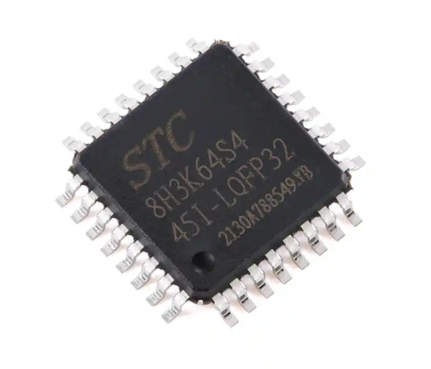
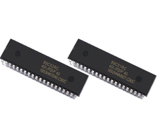
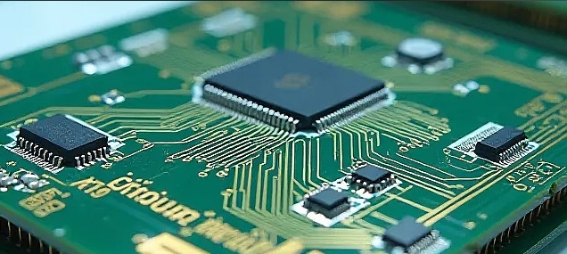
The 8051 microcontroller acts as the central nervous system of the entire operation. It is an 8-bit MCU with a proven history of reliability in control applications. Its relevance in creating an 8051 MCU-controlled DC motor stems from its integrated features. Key among these are the four 8-bit I/O ports (P0, P1, P2, P3), which provide the digital interface to the outside world. The onboard timers/counters are essential for generating the precise Pulse Width Modulation (PWM) signals needed for speed control, while interrupts allow the MCU to respond promptly to external events, such as an emergency stop or an encoder pulse. The 8051 executes the control program stored in its ROM, making decisions based on sensor input or pre-defined algorithms and sending commands to the motor. Its simple instruction set makes it an excellent platform for learning the fundamentals of embedded C or assembly language programming for motor control.
The DC Motor and the Critical Need for a Driver Circuit
A DC motor converts electrical energy into mechanical rotation. However, a fundamental challenge prevents the 8051 from connecting to the motor directly. The 8051’s GPIO pins can typically only source or sink a few milliamps of current, usually in the range of 10-20mA. In contrast, even a small DC motor can require hundreds of milliamps or several amps to start and run under load. Attempting to drive a motor directly from an MCU pin would, at best, result in sluggish performance and, at worst, permanently damage the microcontroller due to overcurrent.
This is where the motor driver circuit becomes non-negotiable. It acts as a current amplifier, taking the low-power control signal from the 8051 and using it to switch a high-power circuit that feeds the motor. The most common and efficient solution for this is an H-Bridge circuit. An H-Bridge, often implemented using a dedicated IC like the L293D or L298N, allows the MCU to control both the direction and speed of the motor. It consists of four switches (transistors or MOSFETs) arranged in an “H” configuration around the motor. By closing specific pairs of switches, the MCU can reverse the voltage polarity across the motor, thereby reversing its direction of rotation.
Supporting Circuitry: Power Supply and Feedback Mechanisms
No 8051 MCU-controlled DC motor system is complete without proper supporting circuitry. A stable and appropriately rated power supply is critical. The system often requires two voltage rails: one for the 8051 logic (typically +5V) and a separate, more powerful one for the motor itself (which could be +6V, +12V, or higher). These supplies must be isolated or properly regulated to prevent motor-induced voltage spikes from resetting or damaging the sensitive MCU.
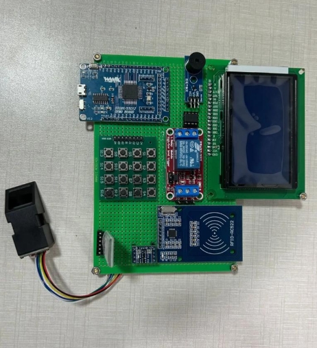
For advanced control, feedback mechanisms are incorporated. The most common is an optical encoder attached to the motor shaft. This encoder generates pulses as the shaft rotates, which are fed back into the 8051’s timer/counter or external interrupt pins. By counting these pulses, the MCU can precisely determine the motor’s speed and position, enabling closed-loop control for applications requiring high accuracy. This transforms a simple open-loop spinner into an intelligent motion control system.
Programming Logic and Control Techniques for Speed and Direction
With the hardware foundation laid, the intelligence of the 8051 MCU-controlled DC motor system is unlocked through software. The program running on the 8051 dictates every aspect of the motor’s behavior.
Digital Control for Direction
Controlling the direction of a DC motor with an H-Bridge driver is fundamentally a digital operation. The 8051 uses two of its I/O pins connected to the “Enable” and “Input” pins of the H-Bridge driver IC.
For example: * Clockwise Rotation: The program sets Pin 1 to HIGH (+5V) and Pin 2 to LOW (0V). * Counter-Clockwise Rotation: The program sets Pin 1 to LOW and Pin 2 to HIGH. * Brake/Fast Stop: The program sets both pins to HIGH or both to LOW (depending on the driver IC’s logic), effectively shorting the motor terminals.
This simple digital output allows for complete and instantaneous directional control, forming the basis of all motion commands in an 8051 MCU-controlled DC motor project.
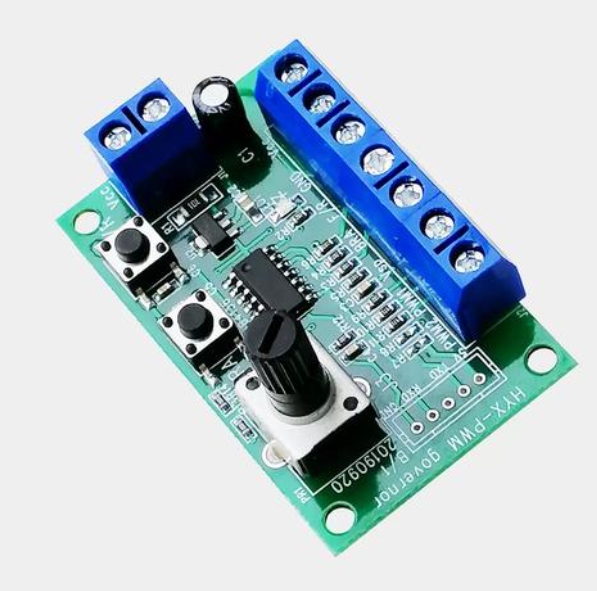
Analog-like Speed Control with Pulse Width Modulation (PWM)
Since the 8051 is a digital device, it cannot natively output an analog voltage to vary the motor’s speed. This is where Pulse Width Modulation (PWM) becomes indispensable. PWM is a technique that mimics an analog signal by rapidly switching a digital output on and off. The key parameter is the duty cycle—the percentage of one period where the signal is high.
A 0% duty cycle (constant LOW) means no power to the motor; it is stopped. A 100% duty cycle (constant HIGH) means full power; the motor runs at maximum speed. A 50% duty cycle (HIGH half the time, LOW half the time) delivers approximately half the average power, resulting in roughly half speed.
The 8051 generates this PWM signal using its built-in timers. The programmer configures a timer to generate an interrupt at a specific frequency. In the Interrupt Service Routine (ISR), an I/O pin is toggled based on a counter that defines the duty cycle. This pin is connected to the “Enable” pin of the H-Bridge driver. Therefore, by simply changing a variable in the code that represents the duty cycle, the programmer can achieve seamless and efficient speed control of an 8051 MCU-controlled DC motor.
Implementing Advanced Control Algorithms
For applications demanding precision, basic open-loop speed control (where you set a PWM value and hope for a certain speed) is insufficient. By integrating feedback from sensors like an encoder, you can implement closed-loop control algorithms directly on the 8051.
The most common is the PID Controller. This algorithm continuously calculates an error value as the difference between a desired setpoint (e.g., target speed) and a measured process variable (e.g., actual speed from the encoder). It then applies a correction based on proportional (P), integral (I), and derivative (D) terms. While computationally intensive for an 8-bit MCU, a well-optimized PID routine can run effectively on an 8051, allowing your 8051 MCU-controlled DC motor system to maintain constant speed under varying loads or achieve precise angular positioning.
Real-World Applications and Enduring Relevance
The principles of building an 8051 MCU-controlled DC motor system are not merely academic; they form the operational basis for a staggering array of devices in our daily lives and industries.
Consumer Electronics and Robotics
This technology is ubiquitous in consumer products. In a typical inkjet printer, multiple 8051 MCU-controlled DC motors are used: one for advancing paper (with roller pressure control), another for moving the print head carriage back and forth with precise positioning, and potentially others for functions like paper feeding or cartridge cleaning. In robotics, these motors are workhorses, driving wheels for mobility in educational robots like line followers or obstacle avoiders, controlling robotic arm joints for pick-and-place tasks, or panning/tilting sensors and cameras in surveillance systems.
Industrial Automation and Automotive Systems
On a larger scale, these concepts scale up to industrial environments. While industrial PLCs often use more powerful processors now, many legacy systems and smaller controllers are based on architectures like that of an enhanced 8051 core used in many modern variants. They control conveyor belt systems—regulating speed and coordinating movement—and operate automated valves and actuators in process control systems.
In automotive applications before modern CAN-bus dominance were numerous instances where dedicated controllers managed functions like power windows (controlling direction and implementing anti-pinch safety features), power seats with memory functions requiring precise positioning using encoders ,and even basic wiper speed controls using PWM techniques derived from these fundamental principles learned through mastering simpler systems first like those built around standard parts found through distributors such as ICGOODFIND.
Conclusion
The journey through designing and implementing an 8051 MCU-controlled DC motor system illuminates fundamental concepts that underpin much of modern mechatronics and embedded control. From understanding current driving limitations necessitating H-Bridge drivers to mastering software techniques like PWM for speed regulation this knowledge remains highly valuable today even with more advanced processors available because it teaches core principles clearly without abstraction layers getting in way initially making it perfect foundation before moving onto complex ARM Cortex-M series devices later down line when needed but starting here ensures solid grasp basics first which will always serve any engineer well regardless how technology evolves around them over time thanks largely due its simplicity yet powerful capabilities when applied correctly within design constraints inherent any project involving physical motion control requirements whether hobbyist level prototype or commercial product development stage needing reliable proven components sourced efficiently from suppliers like ICGOODFIND.