Mastering Servo Motor Control with the 8051 MCU: A Comprehensive Guide
Introduction
The realm of embedded systems and robotics is built upon the precise control of physical components, and few tasks are as fundamental as commanding a servo motor. These versatile actuators are the muscle behind countless applications, from robotic arms and animatronics to camera gimbals and automated guided vehicles. At the heart of many such systems lies a workhorse of the microcontroller world: the 8051. This iconic microcontroller, despite its age, remains a powerful and accessible platform for learning and implementing core embedded concepts. This article serves as an in-depth guide to interfacing and controlling a servo motor using an 8051 MCU, providing you with the theoretical foundation and practical code to bring motion to your projects. We will demystify the communication protocol, delve into the necessary hardware configurations, and provide actionable programming strategies. For engineers and hobbyists seeking reliable components for such implementations, platforms like ICGOODFIND offer a streamlined component sourcing experience, connecting you with a vast inventory of microcontrollers and motors.

Part 1: Understanding the Core Components
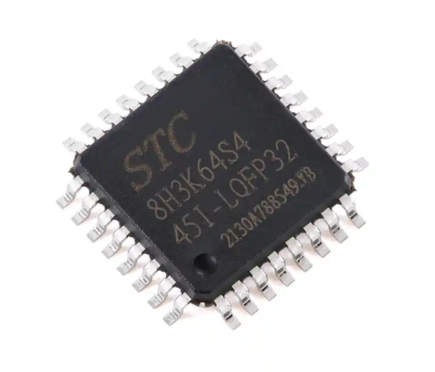
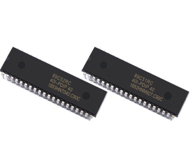
The 8051 Microcontroller Architecture
The 8051 MCU is an 8-bit microcontroller that has stood the test of time due to its simple yet effective architecture. To effectively use it for servo control, one must understand its key features. Central to this task are its timers and I/O ports. The 8051 typically contains two or three 16-bit timers/counters (Timer 0, Timer 1, and sometimes Timer 2). These timers are crucial for generating the precise pulse-width modulated (PWM) signals that servos understand. The microcontroller operates on a clock cycle derived from an external crystal oscillator, often 11.0592 MHz or 12 MHz, which provides the fundamental timing reference for all operations, including the delays and pulse widths we need to generate.
Its four 8-bit I/O ports (P0, P1, P2, and P3) allow it to communicate with the outside world. A single pin from one of these ports, say P1.0, is sufficient to send the control signal to a servo motor. The 8051’s ability to bit-address its ports makes toggling a single pin highly efficient without affecting the others on the same port. Furthermore, its interrupt system allows for creating stable and non-blocking code, ensuring that the crucial servo control pulses are generated consistently while the MCU can perform other tasks.
The Servo Motor Mechanism
A standard hobbyist servo motor is more than just a motor; it’s a closed-loop control system packaged into a small casing. Inside, you’ll find a DC motor, a gear train to reduce speed and increase torque, a potentiometer linked to the output shaft, and a control circuit. The potentiometer provides continuous feedback to the control circuit about the current angular position of the shaft. This is the key to its precision.
The language a servo understands is Pulse Width Modulation (PWM). However, it’s a specific type of PWM. Instead of varying duty cycle to control power, as with a DC motor, the width of a periodic pulse directly correlates to the desired angular position. A standard servo expects a pulse every 20 milliseconds (a 50Hz signal). The width of this pulse dictates the position: * A ~1 ms pulse typically drives the servo to its 0-degree position (full left or counter-clockwise). * A ~1.5 ms pulse typically drives the servo to its 90-degree neutral position. * A ~2 ms pulse typically drives the servo to its 180-degree position (full right or clockwise).
The control circuit inside the servo compares the incoming pulse width with the pulse width generated by its internal potentiometer (which represents the current position). It then drives the motor in the direction that minimizes the difference between these two signals, holding the shaft firmly at the commanded angle.
Part 2: Hardware Interfacing and Circuit Design
Building the Interface Circuit
Connecting an 8051 MCU to a servo motor is remarkably straightforward from a wiring perspective. The servo has three wires: Power (Vcc, usually red), Ground (GND, usually black or brown), and Control/Signal (usually yellow or orange).
The most critical consideration in the hardware design is power supply isolation. Servo motors, especially under load, can draw significant current—far more than the 8051’s I/O pins can supply. Attempting to power the servo directly from the MCU’s power regulator is a common mistake that leads to voltage drops, MCU resets, or permanent damage.
The correct approach is to use a separate power supply for the servo motor. The grounds of the MCU’s circuit and the servo’s power supply must be connected to establish a common reference point. The control signal wire from the 8051 MCU is connected directly to a single I/O pin. This signal is a 5V logic level pulse, which is perfectly compatible with most standard servos. For robust designs, especially with larger servos, using a capacitor across the servo’s power terminals is advisable to smooth out any current spikes caused by the motor starting and stopping.
Signal Generation Fundamentals
Generating the precise PWM signal is the software’s primary responsibility. Since the pulse widths are in the order of milliseconds and must be repeated every 20ms, using a polling method with simple delay loops is possible but inefficient and blocks the MCU from other tasks.
A far superior method is to utilize the 8051’s built-in hardware timers. Here’s how it works conceptually: 1. Timer Initialization: A timer (e.g., Timer 0 or Timer 1) is configured in one of its 16-bit modes. 2. Pulse Start (High): The selected I/O pin is set to high (logic 1), initiating the pulse. 3. Timer for Pulse Width: The timer is loaded with a value calculated to overflow after exactly the desired pulse width (e.g., 1ms for 0 degrees). Upon timer overflow, an Interrupt Service Routine (ISR) is triggered. 4. Pulse End (Low): Inside the ISR, the I/O pin is set to low (logic 0). 5. Timer for Period: The timer is then reloaded with a new value to complete the remainder of the 20ms period. After this second timeout, another ISR triggers, starting the cycle over again by setting the pin high.
This timer-interrupt driven approach is highly accurate and allows the main program loop to execute other code while the servos are being controlled seamlessly in the background.
Part 3: Software Implementation and Code Analysis
Programming Strategies and Timer Configuration
Let’s translate the theoretical signal generation into practical 8051 assembly or C code. Using C is generally more readable and maintainable. The first step is to configure the timer. We’ll assume an 11.0592 MHz crystal.
The timer clock frequency is Crystal Frequency / 12 = 921.6 kHz. The timer increments every 1.085 microseconds (1⁄921.6kHz). To create a delay of ‘X’ microseconds, we need to calculate the initial value for the timer: Initial Value = 65536 - (X / 1.085).
For a 1ms (1000µs) delay: Timer_Value = 65536 - (1000 / 1.085) ≈ 65536 - 922 = 64614 (0xFC66)
For a 2ms (2000µs) delay: Timer_Value = 65536 - (2000 / 1.085) ≈ 65536 - 1843 = 63693 (0xF8CD)
The code would initialize Timer 1 in 16-bit mode (mode 1), enable Timer 1 interrupts, and start the timer.
Sample Code Walkthrough
Below is a simplified C code skeleton using Keil C51 compiler syntax to control a servo on pin P1.0.
#include

sbit Servo = P1^0; // Servo control pin on P1.0

unsigned int High_Time = 1500; // Default to 1.5ms (neutral)
unsigned int Low_Time = 18500; // Default low time for ~20ms period

void Timer1_Init(void) {
    TMOD |= 0x10;   // Set Timer1 in Mode 1 (16-bit)
    ET1 = 1;        // Enable Timer1 Interrupt
    EA = 1;         // Enable Global Interrupt
    Servo = 1;      // Start pulse
    TH1 = (65536 - (High_Time / 1.085)) / 256; // Load high byte
    TL1 = (65536 - (High_Time / 1.085)) % 256; // Load low byte
    TR1 = 1;        // Start Timer1
}

void Timer1_ISR(void) interrupt 3 {
    TR1 = 0; // Stop timer temporarily
    if(Servo == 1) { // If we just finished the high pulse
        Servo = 0;   // Set signal low
        // Reload timer for the low period
        TH1 = (65536 - (Low_Time / 1.085)) / 256;
        TL1 = (65536 - (Low_Time / 1.085)) % 256;
    } else { // If we just finished the low period
        Servo = 1;   // Start new pulse
        // Reload timer for the high pulse
        TH1 = (65536 - (High_Time / 1.085)) / 256;
        TL1 = (65536 - (High_Time / 1.085)) % 256;
    }
    TR1 = 1; // Restart timer
}

void main(void) {
    Timer1_Init();
    while(1) {
        // Main loop can do other things here.
        // To change servo position, simply update 'High_Time'
        // Example: Move to ~0 degrees
        // High_Time = 1000;
        // Low_Time = 19000;
    }
}
This code creates a robust interrupt-driven servo controller where updating High_Time in the main loop will change the servo’s position without disrupting the timing.
Conclusion
Controlling a servo motor with an 8051 MCU is an excellent project that solidifies one’s understanding of embedded systems fundamentals: hardware interfacing, timer operation, interrupt handling, and PWM signal generation. While modern microcontrollers like ARM Cortex-M cores offer more power and peripherals, mastering these concepts on th e straightforward 8051 architecture provides an invaluable foundation. The principles of generating precise timing signals and managing power requirements are universally applicable across all microcontroller platforms. By leveraging interrupts for signal generation, you create efficient and responsive systems capable of controlling multiple servos or performing other concurrent tasks. For those embarking on this or similar electronic design journeys, efficiently sourcing reliable components is key. Platforms like ICGOODFIND serve as an excellent resource for finding authentic microcontrollers, servo motors, and development tools, ensuring your projects are built on a foundation of quality components.