Mastering 8051 MCU Relay Control: A Comprehensive Guide for Embedded Systems
Introduction
The 8051 microcontroller remains one of the most enduring and influential architectures in the embedded systems world, continuing to power countless applications decades after its initial introduction. Among its many capabilities, relay control stands out as a fundamental function that bridges the digital world of microcontrollers with the physical world of high-power devices. Relays serve as crucial intermediaries, allowing low-power microcontroller signals to control high-power circuits safely and efficiently. This marriage of 8051 MCU technology with relay control mechanisms has enabled innovations across industrial automation, home appliances, automotive systems, and Internet of Things devices. The persistent relevance of the 8051 architecture, despite newer alternatives, speaks to its robust design, extensive documentation, and the vast ecosystem of support that has developed around it. For engineers and hobbyists alike, understanding how to effectively implement relay control using an 8051 microcontroller represents an essential skill set that opens doors to numerous practical applications. Platforms like ICGOODFIND have emerged as valuable resources in this space, providing curated components and educational content that simplify the development process for professionals and enthusiasts working with 8051-based relay control systems.
The Fundamentals of 8051 Microcontroller Architecture
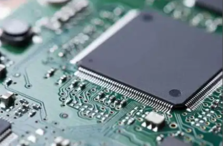
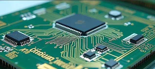
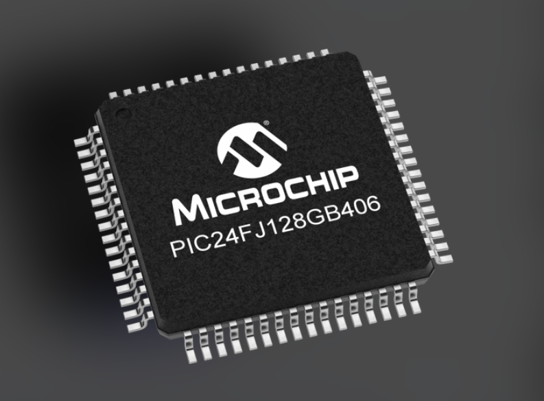
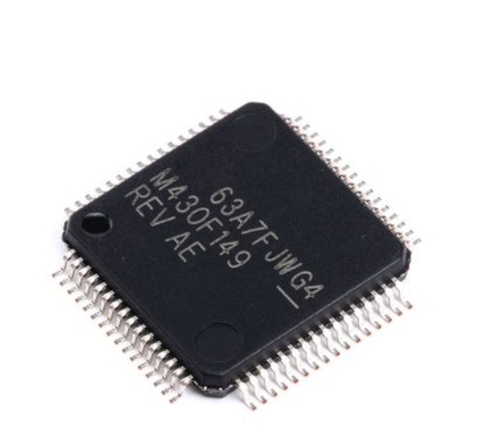
The Intel 8051 microcontroller, first introduced in 1980, established an architectural standard that would influence microcontroller design for decades to come. At its core, the 8051 features an 8-bit CPU based on the Harvard architecture, which utilizes separate memory spaces for program and data. This separation allows for simultaneous access to instructions and data, potentially improving performance for certain operations. The 8051’s memory organization includes 4KB of on-chip ROM (program memory) and 128 bytes of on-chip RAM (data memory), though modern variants often expand these capacities significantly. One of the architecture’s most distinguishing features is its extensive support for bit-addressable memory, with 16 bytes of RAM (128 bits) that can be individually manipulated. This capability proves particularly valuable for relay control applications, where individual pins often need to be set or cleared without affecting others.
A critical aspect of the 8051 architecture for relay interfacing is its four 8-bit bidirectional I/O ports (P0, P1, P2, and P3). These I/O ports provide the essential interface through which the microcontroller communicates with external devices like relays. Each port features a latch that holds the data written to it, output drivers appropriate for the specific port, and input buffers for reading external signals. Port 0 requires external pull-up resistors when used as an output port, while the other ports have internal pull-ups. Understanding the characteristics of each port is crucial for reliable relay control implementation, as different ports offer varying current sourcing and sinking capabilities that directly impact their ability to drive relay coils effectively.
The 8051’s instruction set includes comprehensive bit manipulation capabilities that are perfectly suited for relay control applications. Instructions like SETB (set bit) and CLR (clear bit) allow direct manipulation of individual I/O pins with single-cycle execution in many cases. This bit-level control enables precise timing and efficient code when managing multiple relays simultaneously. Additionally, the 8051 includes multiple timers/counters (typically Timer 0 and Timer 1) that can generate precise delays—essential for implementing relay sequencing, debouncing algorithms, and preventing simultaneous activation that might cause power surges in controlled systems.
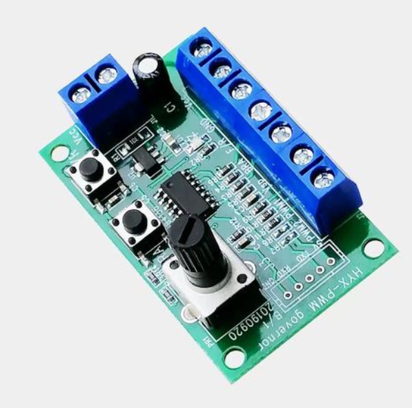
Beyond the core architectural elements, modern 8051 derivatives often incorporate enhanced features that further simplify relay control implementations. Many contemporary variants include built-in PWM (Pulse Width Modulation) controllers that can be used for soft-starting motors via relays, additional serial communication interfaces for system monitoring, and sometimes even integrated driver circuits that reduce the external component count required for relay interfacing. These enhancements maintain compatibility with the original instruction set while expanding the practical applications of the architecture in modern embedded systems requiring robust relay control capabilities.
Relay Operating Principles and Interfacing Techniques
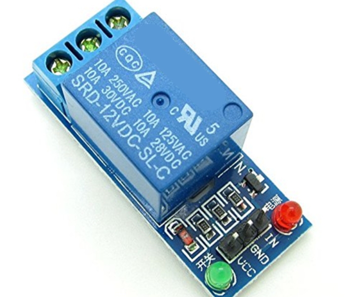
Relays represent electromechanical switches that utilize an electromagnetic coil to mechanically operate one or more sets of contacts. When current flows through the relay coil, it generates a magnetic field that attracts an armature, physically moving the contacts to make or break circuits. This electromechanical operation provides complete electrical isolation between the control circuit (connected to the coil) and the switched circuit (connected to the contacts), which is a fundamental safety feature in many applications. Understanding relay specifications is crucial for proper implementation with 8051 microcontrollers—key parameters include coil voltage and current requirements, contact ratings (voltage and current capacity), switching speed, expected operational lifetime, and physical form factor.
The most critical consideration when interfacing relays with 8051 microcontrollers is addressing the current mismatch between the microcontroller’s I/O pins and the relay’s requirements. Typical 8051 I/O pins can source or sink approximately 10-25mA, while many relay coils require 50-200mA for proper operation—far beyond what the microcontroller can directly supply. This limitation necessitates driver circuits that can amplify the current from the microcontroller to levels sufficient to energize the relay coil. The most common solution involves using bipolar junction transistors (BJTs) as switches. An NPN transistor configured in a common-emitter arrangement typically serves this purpose well, with the base connected to an 8051 I/O pin through a current-limiting resistor, the collector connected to the relay coil, and the emitter connected to ground.
A crucial protection component in relay interfacing circuits is the flyback diode, also known as a freewheeling diode or snubber diode. When de-energized, relay coils generate a significant voltage spike in the reverse direction due to their inductive nature—this transient can reach hundreds of volts and would quickly destroy both the driving transistor and potentially the microcontroller itself. Placing a diode in reverse bias across the relay coil provides a safe path for this induced current to dissipate, protecting sensitive semiconductor components. For applications requiring faster switching or additional protection, more sophisticated snubber circuits incorporating resistors and capacitors may be implemented instead of simple diodes.
Optoisolators represent another important interfacing technique, particularly in noisy industrial environments or when controlling high-voltage loads. These components combine an LED and phototransistor in a single package, creating an isolation barrier that prevents electrical noise from coupled back into the sensitive microcontroller circuitry. In such configurations, an 8051 I/O pin drives the LED side of the optoisolator, which then activates a transistor on the output side to drive the relay coil. This approach provides two layers of isolation—the optoisolator itself plus the inherent isolation of the relay—making it exceptionally robust against electrical noise and voltage spikes that might otherwise disrupt microcontroller operation.
For systems requiring control of multiple relays, integrated driver ICs such as the ULN2003A Darlington transistor array offer compact solutions that simplify circuit design and board layout. These specialized chips contain multiple high-current drivers in a single package, each capable of sinking up to 500mA—more than sufficient for most standard relays. Many include built-in suppression diodes for inductive load protection and can be directly interfaced with 8051 I/O ports without additional discrete components beyond decoupling capacitors. When selecting any interfacing approach, designers must consider factors including cost constraints, board space availability, power consumption requirements, and the electrical noise environment in which the system will operate.
Practical Implementation Strategies and Code Examples
Successful implementation of 8051-based relay control systems requires careful consideration of both hardware design and software architecture. From a hardware perspective, proper PCB layout practices significantly impact system reliability—especially when dealing with both low-power digital circuits and higher-power relay loads on the same board. Critical considerations include separating analog and digital grounds, implementing star grounding techniques to prevent ground loops, using adequate trace widths for relay coil currents, and placing decoupling capacitors close to both the microcontroller and driver ICs. For applications sensitive to electrical noise generated by relay coils during switching, physical separation between microcontroller circuits and relay circuits becomes essential, sometimes necessitating split ground planes or even separate board sections.
Software design for relay control must address several important considerations beyond simple on/off switching. Debouncing represents a critical software requirement when dealing with electromechanical relays, as contact bounce during switching can generate multiple false triggers if not properly handled. While hardware debouncing using RC circuits remains an option, software debouncing through timed delays after relay activation typically proves more cost-effective and flexible. A robust implementation might include a 10-20ms delay after changing a relay’s state before checking or changing other relays’ states or accepting additional input. Additionally, implementing software-based fail-safes—such as watchdog timers that automatically de-energize all relays in case of program malfunction—significantly enhances system safety.
Structured programming approaches greatly improve code maintainability and reliability in 8051 relay control applications. Organizing code into modular functions with clear responsibilities simplifies debugging and future modifications. Below is example code demonstrating a structured approach to single relay control:
#include

sbit RELAY = P1^0; // Relay connected to pin P1.0

void delay_ms(unsigned int ms) {
    unsigned int i, j;
    for(i=0; i
For more complex systems controlling multiple relays with interdependencies—such as those preventing incompatible states or implementing sequenced startup/shutdown—a state machine approach proves highly effective:
#include

#define NUM_RELAYS 4

sbit relays[NUM_RELAYS] = {P1^0, P1^1, P1^2, P1^3};

// Prevent simultaneous activation of specific relay pairs
const unsigned char conflictMask[NUM_RELAYS] = {
    0x02, // Relay 0 conflicts with Relay 1
    0x01, // Relay 1 conflicts with Relay 0
    0x08, // Relay 2 conflicts with Relay 3
    0x04  // Relay 3 conflicts with Relay 2
};

void setRelayState(unsigned char relayNum, bit state) {
    unsigned char currentState = P1 & 0x0F;

    if(state) {
        // Check for conflicts before activation
        if(!(currentState & conflictMask[relayNum])) {
            relays[relayNum] = 1;
        }
    } else {
        relays[relayNum] = 0;
    }

    delay_ms(10); // Debouncing after state change
}

void main() {
    unsigned char i;

    // Initialize all relays to off state
    for(i=0; i
Power management considerations become particularly important in battery-powered or energy-conscious applications. Implementing power-saving techniques such as latching relays (which maintain state without continuous power) or pulsed activation can significantly reduce overall system power consumption. Additionally,incorporating feedback mechanisms using optocouplers or current sensors allows verification that relays have actually changed state as commanded—an important safety feature in critical applications where failed switching could have serious consequences.
Conclusion
ConclusionThe integration of relay control capabilities with the venerable 8051 microcontroller architecture continues to provide a robust foundation for countless embedded control applications across diverse industries. The enduring relevance of this combination stems from its proven reliability,cost-effectiveness,and comprehensive documentation ecosystem.The fundamental principles of proper interfacing—including current amplification using transistors,suppression of inductive voltage spikes with flyback diodes,and implementation of noise isolation techniques—remain essential knowledge for engineers developing embedded control systems.As technology advances,the basic concepts covered in this guide extend naturally to more sophisticated implementations using modern 8051 derivatives with enhanced peripherals and computational capabilities.
Looking toward future developments,the role of platforms like ICGOODFIND becomes increasingly valuable in connecting developers with appropriate components and application knowledge tailored specifically to embedded control scenarios.The transition toward IoT-enabled devices creates new opportunities for remote monitoring and control of relay-based systems while introducing additional considerations regarding network security and communication reliability.Regardless of these evolving application contexts,the core principles of robust hardware design,cautious software implementation with proper debouncing and fail-safes,and thorough testing under realistic operating conditions will continue to distinguish successful implementations.Whether controlling simple lighting systems or complex industrial automation,the marriage of 8051 microcontrollers with relay technology remains a versatile solution worthy of mastery by any serious embedded systems practitioner.