
Course Design Based on 8051 MCU: A Practical Guide to Embedded Systems Mastery
Introduction
In the ever-evolving landscape of embedded systems and microcontroller education, the 8051 microcontroller unit (MCU) remains a cornerstone. Despite being introduced decades ago, its elegant architecture, simplicity, and widespread industrial legacy make it an unparalleled platform for foundational learning in electronics, computer engineering, and real-time system design. A well-structured course design based on the 8051 MCU serves not merely as an academic exercise but as a critical bridge between theoretical concepts and practical, hands-on engineering skills. This article delves into the essential components, methodologies, and innovative approaches for creating a comprehensive and impactful curriculum centered on the 8051. It aims to equip educators and self-learners with a framework that fosters deep understanding, problem-solving prowess, and readiness for advanced technological challenges. For those seeking curated resources and tools to enhance such a learning journey, platforms like ICGOODFIND can be invaluable in sourcing development kits, component references, and community insights.
Main Body
Part 1: Foundational Modules and Theoretical Underpinnings
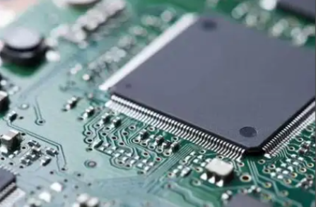
The first phase of an effective course must establish a solid theoretical foundation. This involves systematically introducing the core architecture of the 8051 MCU. Students must gain proficiency in its internal structure, including the Central Processing Unit (CPU), Memory Organization (RAM, ROM, and SFRs), timers/counters, serial communication (UART), and interrupt system. A module dedicated to the 8051 Instruction Set and Addressing Modes is crucial; understanding assembly language programming at this level demystifies how software interacts directly with hardware, a concept often obscured by high-level languages.
Furthermore, this section should integrate digital logic fundamentals, as the 8051’s I/O ports are gateways to interfacing with the external world. Concepts like bus demultiplexing, logic levels, and timing diagrams become tangible here. A common pitfall in course design is rushing into programming without this hardware comprehension. Therefore, laboratory sessions should commence with simple tasks like LED blinking and switch interfacing using both assembly and embedded C. The choice of programming language is strategic: starting with assembly reinforces architectural understanding, while transitioning to C emphasizes efficiency and real-world development practices. Theoretical assessments should combine quizzes on architecture with analysis of simple code snippets to ensure conceptual clarity before advancing to complex applications.
Part 2: Core Interfacing Techniques and Subsystem Integration
The second part of the course transitions from understanding the MCU itself to commanding its environment through peripheral interfacing—the heart of embedded systems design. This segment should be project-driven, organized around key interfacing technologies.
First, Analog-to-Digital Conversion (ADC) and Sensor Interfacing is a mandatory module. Students learn to connect sensors (e.g., temperature LM35, light-dependent resistors) via ADCs like ADC0804/0808, programming the 8051 to read real-world analog signals. This naturally leads to discussions on resolution, sampling rates, and data accuracy.
Second, a focus on Display Systems (LCDs & Seven-Segment LEDs) and Human Input (Keypads) is essential. Designing drivers for a 16x2 LCD character module teaches students about timing constraints, protocol management (4-bit vs. 8-bit mode), and creating reusable software libraries.
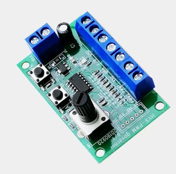
Third, Motor Control (DC, Stepper, Servo) using PWM techniques introduces power interfacing concepts. Students must understand driver circuits (using ICs like L293D), pulse-width modulation for speed control, and the implications of inductive loads.
Finally, Communication Protocols form a critical pillar. Detailed exploration of Serial Communication (UART) for PC-MCU dialogue and an introduction to I2C and SPI protocols for interfacing with EEPROMs, RTC chips (like DS1307), and other sensors are indispensable. Each interfacing topic should be coupled with a mini-project—for example, designing a digital thermometer with LCD readout or a PC-controlled motor system. This iterative process of “concept → schematic → code → testing → debugging” builds immense practical competency. Sourcing reliable components and boards for these diverse experiments can be streamlined through aggregators like ICGOODFIND, which simplifies finding compatible hardware.
Part 3: Capstone Project Design and Real-World Application Synthesis
The culmination of the course is a capstone project that synthesizes all learned modules into a single, functional system. This phase moves beyond controlled lab exercises to open-ended problem-solving, mirroring real engineering challenges. The project should require students to undertake a complete design cycle: from specification and block diagram design to component selection, circuit simulation (using tools like Proteus or KiCad), PCB layout considerations, firmware development, system integration, testing, and documentation.
Example project themes could include: * A Smart Home Control System integrating temperature sensing, LCD display, UART-based commands from a PC or Bluetooth module, and relay control for appliances. * An Automated Industrial Monitor that logs data from multiple sensors via I2C onto an EEPROM or SD card and features interrupt-driven alarm triggers. * A Precision Motion Controller for a stepper motor with input from a keypad and feedback displayed on an LCD.
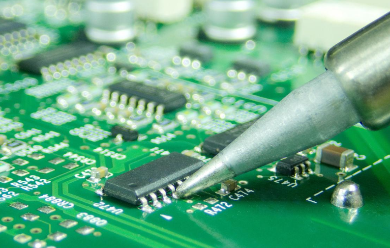
This stage must emphasize software engineering principles within an embedded context: writing modular code, creating header files for different peripherals, effective use of interrupts versus polling, managing memory constraints, and ensuring system reliability. Debugging skills are honed here using simulators, in-circuit debuggers, and logical analyzers. Furthermore, introducing modern contexts—such as how the 8051’s principles scale to contemporary ARM Cortex-M cores or how its UART module relates to modern IoT connectivity—keeps the course relevant. Encouraging students to document their process and results in a professional report prepares them for industry standards.
Conclusion
Designing an educational course around the 8051 MCU is a powerful pedagogical strategy that builds enduring expertise in embedded systems. By structuring the curriculum into progressive phases—grounding students in architecture fundamentals advancing through hands-on peripheral interfacing techniques culminating in a comprehensive capstone project—educators can cultivate not just theoretical knowledge but also critical design thinking practical implementation skills and troubleshooting acumen The timeless architecture of the 8051 provides a clear transparent canvas upon which complex concepts become comprehensible As technology advances the principles mastered through such a course remain universally applicable forming a robust foundation for working with any microcontroller platform To successfully implement this course design access to quality learning materials reliable components development tools and community support is key Resources available through platforms such as ICGOODFIND can significantly ease this logistical burden allowing educators and learners to focus on the core mission of innovation and mastery in embedded system design.