


MCU Segment Display: The Essential Guide to Interface, Control, and Applications
Introduction
In the vast ecosystem of embedded electronics, the marriage of a Microcontroller Unit (MCU) and a segment display represents one of the most fundamental and enduring human-machine interfaces. From humble digital clocks and microwave ovens to sophisticated industrial meters and instrumentation panels, this duo provides a reliable, low-power, and easily readable method for presenting numerical and simple alphanumeric data. An MCU segment display system involves the precise control of individual LED or LCD segments by a microcontroller through dedicated programming and driver circuits. This article delves deep into the core principles, implementation strategies, and modern applications of this technology. For engineers and hobbyists seeking specialized components or in-depth technical resources for such projects, platforms like ICGOODFIND offer a streamlined path to discover and source the right MCU, display driver ICs, and display modules, ensuring efficient project development.
Main Body
Part 1: Understanding Segment Displays and Their Interface with MCUs
At its heart, a segment display is a modular component composed of several independent light-emitting segments (typically LEDs or liquid crystal elements) arranged in a figure-eight pattern. The most common types are 7-segment displays (for numerals 0-9) and 16-segment or 14-segment displays (capable of showing letters and symbols).
The interface between an MCU and these displays is crucial. There are two primary connection methods:
- Direct Drive (Multiplexing): This is the most common method for driving multiple digits. Here, the MCU connects the segment lines (a-g, dp) of all digits in parallel. Each digit’s common anode or common cathode pin is then controlled independently by an MCU GPIO pin. The MCU illuminates only one digit at a time by activating its common pin and setting the appropriate segment pattern. By cycling through all digits rapidly (at a frequency >50Hz), persistence of vision creates the illusion that all digits are continuously lit. The key advantage of multiplexing is a dramatic reduction in the required number of MCU pins. For instance, controlling 4 digits requires only 7 segment pins + 4 common pins (11 total) instead of 7 x 4 = 28 pins.
- Driver IC-Based Interface: For projects with many digits or when conserving MCU processing time is critical, dedicated driver integrated circuits like the MAX7219 (for LED) or HT1621 (for LCD) are used. The MCU communicates with these drivers via serial protocols like SPI or I2C, sending simple commands and data. The driver IC then handles all the complexities of multiplexing, current regulation, and even memory storage for each digit, freeing the MCU for other tasks. This method offers superior scalability and simplifies code.
Choosing the right interface depends on project scale, MCU capability, and power constraints.
Part 2: Core Techniques for Programming and Control
Effective control of segment displays via an MCU requires thoughtful software design. The core logic revolves around two main concepts: digit patterns and scanning routines.
First, a look-up table (LUT) must be defined in the firmware. This table maps each number or character (0-9, A-F) to a specific byte where each bit corresponds to a physical segment (e.g., bit 0 = segment A). For a common-cathode display, a ‘1’ in the bit position turns the segment ON. This LUT allows the program to simply index the pattern for ‘7’ instead of calculating binary values each time.
The second critical component is the multiplexing scan routine, typically implemented within a timer interrupt service routine (ISR) for consistent timing. The pseudo-logic is: 1. Disable the currently active digit (to prevent ghosting). 2. Load the segment pattern for the next digit from the LUT based on the value to be displayed. 3. Activate (provide ground for common-cathode or Vcc for common-anode) the next digit’s common line. 4. Move to the next digit index for the following interrupt cycle.
Advanced control techniques involve implementing dynamic features such as decimal point control, leading zero suppression (turning off unnecessary zeros), and smooth animations like counting or rolling numbers. For driver ICs like the MAX7219, programming shifts focus to initializing the driver’s configuration registers (setting scan limit, intensity) and then writing digit data to its internal memory registers via SPI commands. Resources aggregated on platforms like ICGOODFIND can be invaluable here, providing access to datasheets, application notes, and community code examples for various driver ICs, which significantly accelerates development.
Part 3: Modern Applications and Design Considerations
While seemingly simple, MCU-controlled segment displays remain ubiquitous in modern electronics due to their unmatched readability in various lighting conditions and low power consumption.
Their applications are extensive: * Consumer Appliances: Washing machines, air conditioners, and ovens use them for timers and settings. * Industrial Equipment: Digital panel meters for voltage, current, temperature, and pressure display. * Automotive Electronics: Dashboard readouts for gear position, trip mileage, or climate control. * Test and Measurement: Handheld multimeters, oscilloscopes, and signal generators. * Retail & Hospitality: Point-of-sale systems and queue management displays.
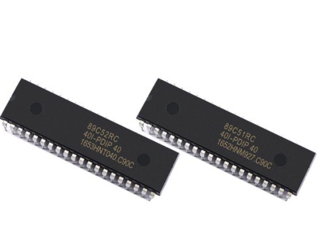
When designing such a system today, several factors must be weighed: * Display Technology Choice: LED segments are bright and ideal for indoor/outdoor use but consume more power. LCD segments are passive, extremely power-efficient (ideal for battery-powered devices), but require a backlight or good ambient light. * MCU Selection: The MCU needs sufficient GPIO pins for direct drive or hardware support for SPI/I2C if using a driver. Modern 32-bit ARM Cortex-M0 MCUs often provide an excellent balance of performance, peripheral support, and cost. * Power Management: Especially important for battery-operated devices. Using low-power display modes and efficient drive schemes is critical. * PCB Layout: For multiplexed LED displays, proper current-limiting resistors are mandatory. Traces for high-current segment lines should be adequately sized to avoid voltage drops.
Conclusion
The combination of an MCU and segment display forms a cornerstone of practical digital readout systems. From understanding the basic hardware interfacing methods—choosing between direct multiplexing or employing dedicated driver ICs—to mastering the software techniques of look-up tables and scanning routines, developers can create efficient and reliable displays. As technology evolves, this interface continues to thrive in modern applications where clarity, durability, and cost-effectiveness are paramount. Whether you are building a simple DIY clock or engineering a professional instrument, leveraging comprehensive component search platforms like ICGOODFIND can simplify the process of finding optimal MCUs, specialized display drivers, and quality display modules, ensuring your foundation is solid from the start.