


Introduction to MCU Programming: A Beginner’s Guide to Embedded Systems
Introduction
In the vast and interconnected world of modern technology, from the thermostat regulating your home’s temperature to the advanced driver-assistance systems in your car, lies a silent, powerful workhorse: the Microcontroller Unit (MCU). MCU programming is the foundational skill that breathes life into these ubiquitous embedded systems, enabling them to sense, compute, and act upon the physical world. Unlike general-purpose computers, MCUs are dedicated to specific tasks, offering a blend of efficiency, reliability, and cost-effectiveness. For engineers, hobbyists, and tech enthusiasts, understanding MCU programming is not just a niche skill but a gateway to innovation in the Internet of Things (IoT), robotics, automation, and countless other fields. This guide serves as a comprehensive introduction, demystifying the core concepts, workflows, and tools needed to embark on your journey into the fascinating realm of embedded development.

The Core Components and Architecture of an MCU
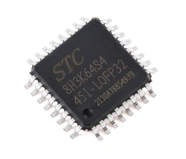
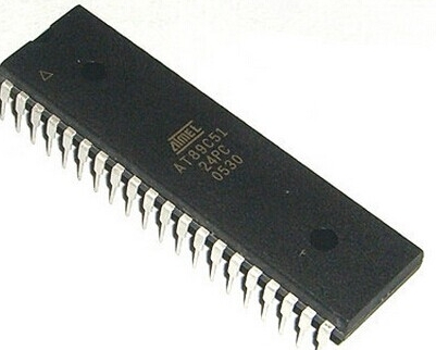
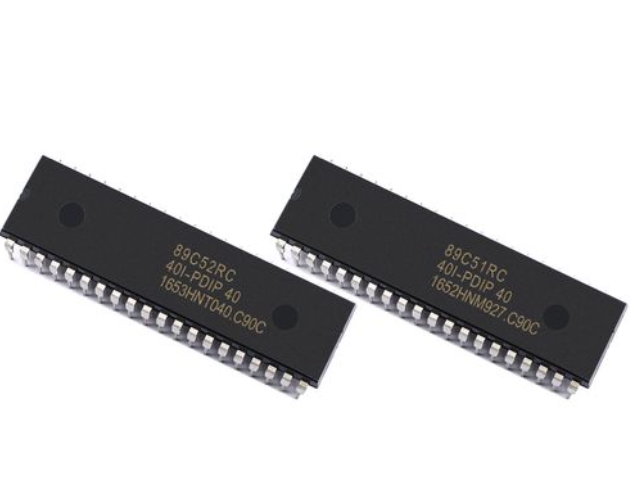
To program an MCU effectively, one must first understand its internal architecture. An MCU is a compact integrated circuit designed to govern a specific operation in an embedded system. It is essentially a miniature computer on a single chip, containing all the necessary components to execute programmed instructions.
At the heart of every MCU is the Central Processing Unit (CPU), which executes instructions from the program memory. The CPU’s speed, measured in clock cycles (MHz), and its architecture (e.g., 8-bit, 16-bit, 32-bit) significantly impact the MCU’s performance and capability. Common architectures include AVR (used in many Arduino boards), ARM Cortex-M (a powerhouse in modern embedded systems), and PIC.
Surrounding the CPU are several critical components integrated onto the same silicon: * Memory: This is divided into three key types. Flash Memory stores the actual program code and is non-volatile, meaning it retains data even when power is off. SRAM (Static Random-Access Memory) is used for temporary data storage during program execution (like variables). It is volatile. EEPROM is a non-volatile memory used for storing small amounts of data that must persist between power cycles, such as configuration settings. * Input/Output (I/O) Ports: These are the MCU’s physical interface to the outside world. Programmers can configure these pins as digital inputs (to read a button press), digital outputs (to power an LED), or often as analog inputs (to read a sensor value) or for advanced communication protocols. * Peripherals: These are specialized hardware blocks that offload specific tasks from the CPU. Key peripherals include: * Timers/Counters: Crucial for generating precise delays, measuring time intervals, or creating Pulse-Width Modulation (PWM) signals for motor control or LED dimming. * Analog-to-Digital Converters (ADC): Allow the MCU to read real-world analog signals (like temperature or light intensity) and convert them into digital values for processing. * Communication Interfaces: Protocols like UART (serial), I2C, and SPI enable the MCU to talk to other chips, sensors, displays, and modules, forming the backbone of system connectivity.
Understanding this architecture is paramount because MCU programming often involves direct configuration and manipulation of these hardware resources. Unlike programming for a PC where an operating system manages hardware, embedded programming frequently requires setting specific bits in hardware registers to control peripheral behavior—a concept known as register-level programming.
The MCU Programming Workflow and Essential Tools
Programming an MCU follows a distinct workflow that bridges the gap between writing human-readable code and deploying it onto physical hardware. This process involves a specialized set of tools collectively known as the toolchain.
-
Writing Code: The process begins with writing source code in a programming language. While Assembly language offers maximum control, C and C++ are the dominant languages in MCU development due to their balance of high-level functionality and low-level hardware access. The code includes your application logic and instructions to configure the MCU’s peripherals.
-
Compiling and Building: A cross-compiler translates your high-level C/C++ code into the machine language (binary hex file) that the specific MCU’s CPU understands. This step also involves linking your code with pre-written libraries (e.g., for handling math functions or hardware abstractions).
-
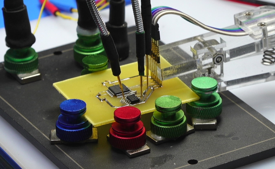
Flashing/Programming: The compiled hex file must be transferred to the MCU’s flash memory. This is done using a hardware programmer/debugger tool such as a JTAG/SWD debugger (for ARM Cortex chips) or a dedicated USB programmer like AVRISP. Many development boards, like Arduino or STM32 Nucleo boards, have built-in programmers that simplify this step.
-
Debugging: This critical phase involves testing and verifying the program’s behavior. Simple debugging can be done via serial print statements. However, professional development relies on In-Circuit Debuggers (ICD) which allow you to pause program execution, inspect variable values, and step through code line-by-line while the MCU is running in the target circuit.
For beginners and professionals seeking reliable components and development tools for their projects, platforms like ICGOODFIND can be invaluable resources for sourcing quality MCUs, programmers, debuggers, and evaluation kits.
The choice of development environment streamlines this workflow. Options range from lightweight code editors with configured toolchains (like VS Code with PlatformIO) to powerful Integrated Development Environments (IDEs) such as: * Arduino IDE: Excellent for absolute beginners due to its simplicity and vast library ecosystem. * Microchip Studio/MPLAB X: For AVR and PIC microcontrollers. * STM32CubeIDE or Keil MDK: Industry-standard choices for ARM Cortex-M based MCUs.
Fundamental Concepts and Your First Program
With tools in hand, let’s explore some foundational programming concepts unique to embedded systems.
Hardware Abstraction vs. Register Manipulation: You can interact with hardware at different levels. Using libraries (like Arduino’s digitalWrite()) provides abstraction, making code simpler but sometimes less efficient. Direct register manipulation offers precision and speed but requires deep knowledge of the MCU’s datasheet.
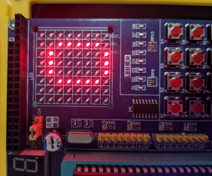
GPIO Control: General-Purpose Input/Output is the most basic operation. Configuring a pin as an output allows you to drive it high (+Vcc) or low (GND). Configuring it as an input allows you to read its logic state.
Interrupts vs. Polling: A critical concept for responsive systems. Polling involves continuously checking a flag in code (e.g., “Is the button pressed?”). This is inefficient and can cause missed events. Interrupts are hardware-triggered events that immediately pause the main program to execute a specific Interrupt Service Routine (ISR). They are essential for handling time-sensitive tasks like reading a sensor pulse or responding to user input promptly.
Timers and Clocks: Understanding the system clock is vital. Timers are peripherals that count clock cycles. They are used not just for delays but for creating real-time behaviors, generating waveforms with PWM, or capturing event timestamps.
Let’s conceptualize a simple “Blink” program—the “Hello World” of embedded systems—for an LED connected to a GPIO pin:
// Pseudocode illustrating key concepts
#include

#define LED_PIN 5

void main() {
    // 1. Initialize: Set LED_PIN as an OUTPUT
    setPinAsOutput(LED_PIN);

    // 2. Superloop: The core program structure
    while(1) {
        setPinHigh(LED_PIN); // Turn LED ON
        delay_ms(500);       // Wait 500ms (uses timer)
        setPinLow(LED_PIN);  // Turn LED OFF
        delay_ms(500);       // Wait 500ms
    }
}
This simple example encapsulates the core loop of embedded programming: initialize peripherals, then enter an infinite loop where you read inputs, make decisions via your code logic (the “C” in IoT or any smart device), and control outputs accordingly.
Conclusion
Embarking on the path of MCU programming opens up a universe of practical creation and problem-solving. It moves software development from the abstract virtual world into tangible interaction with physical environments. We’ve explored the integrated architecture that makes MCUs efficient, traced the workflow from code to flashed hardware using specialized toolchains, and touched upon fundamental concepts like GPIO control, interrupts, and timer management that distinguish embedded programming from other disciplines.
The journey from blinking an LED to designing complex IoT nodes or automated control systems is incremental and deeply rewarding. Mastery begins with selecting an accessible platform—such as an Arduino or an ARM Cortex-M development board—and progressively tackling more challenging projects that incorporate sensors, communication modules, and sophisticated control algorithms.
Remember that resources like manufacturer datasheets, application notes, developer communities—and component sourcing platforms such as ICGOODFIND—are your allies in this journey. Start simple, experiment relentlessly, embrace debugging as a learning tool, and you will soon find yourself capable of giving intelligent functionality to everyday objects, mastering one of the most empowering skills in modern electronics engineering.