


Working Principle of MCU Development Board
Introduction
In the rapidly evolving world of embedded systems and electronics, the Microcontroller Unit (MCU) Development Board stands as a fundamental tool for engineers, hobbyists, and students alike. Serving as a bridge between abstract code and tangible hardware, these boards transform theoretical concepts into functional prototypes and final products. Understanding the working principle of an MCU development board is crucial for anyone looking to harness the power of embedded computing. This article delves into the core mechanisms that make these boards operate, exploring the synergy between hardware components and software instructions. We will demystify how a simple piece of code translates into actions like lighting an LED, reading a sensor, or communicating with other devices. By grasping these principles, developers can move beyond basic tutorials to create innovative and efficient solutions. Notably, platforms like ICGOODFIND provide invaluable resources for comparing components, sourcing development boards, and accessing technical data, significantly streamlining the development process.
Main Body
Part 1: The Architectural Foundation – Core Components and Their Roles
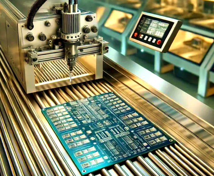
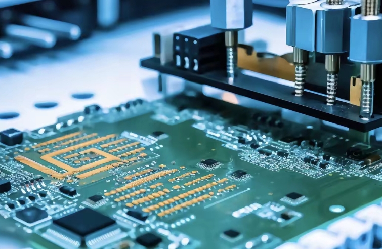
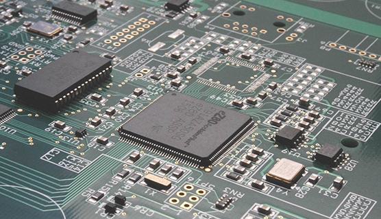
At its heart, an MCU development board is a printed circuit board (PCB) that hosts a microcontroller chip and all the necessary supporting circuitry to make it operational and accessible. The working principle begins with understanding this ecosystem of components.
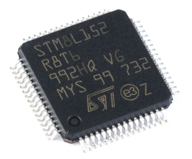
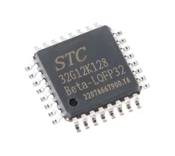
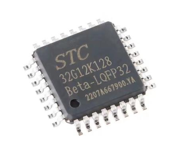
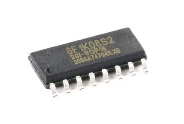
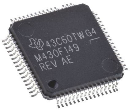
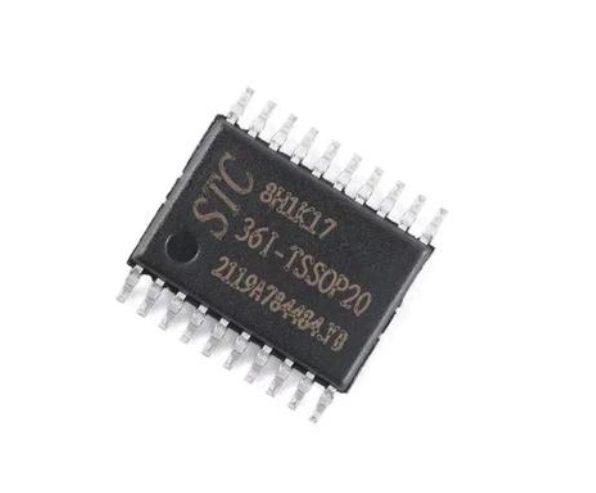
The central element is the Microcontroller Unit (MCU) itself. This is a compact integrated circuit designed to govern a specific operation in an embedded system. It incorporates a processor core (like ARM Cortex-M, AVR, or PIC), memory (Flash for program storage, RAM for data), and programmable input/output peripherals all on a single chip. The MCU executes software instructions stored in its memory to control connected hardware.
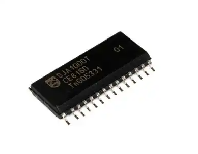
Surrounding the MCU are critical support components: * Power Supply Circuitry: This includes voltage regulators and filtering capacitors that convert an external power source (e.g., USB, battery) into the stable, clean voltages required by the MCU and other onboard components (e.g., 3.3V or 5V). Reliable power is the first principle of operation. * Clock Circuit: An MCU requires a timing reference to synchronize its operations. This is provided by a crystal oscillator or ceramic resonator. Every instruction cycle is tied to this clock pulse, determining the speed of execution. * Programming/Debug Interface: Circuits for ICSP (In-Circuit Serial Programming) or JTAG/SWD interfaces allow the developer to upload compiled code from a computer to the MCU’s Flash memory. This is the gateway through which software meets hardware. * Basic I/O Facilities: Most boards include user-friendly elements like push buttons, LEDs, and potentiometers for basic interaction without requiring external components for initial testing. * Communication Transceivers: Components like USB-to-Serial chips (e.g., FTDI, CH340) enable serial communication between the board and a PC for data exchange and debugging.
The principle here is integration: the development board provides a ready-made, stable hardware platform where the developer can focus on software, confident that the foundational electrical requirements—power, timing, and programming—are already correctly implemented.
Part 2: The Execution Cycle – From Code to Action
The true essence of the working principle unfolds in the execution cycle of the MCU. Once powered and clocked, the MCU begins a relentless fetch-decode-execute cycle managed by its central processor.
- Fetch: The processor retrieves the next machine-language instruction from its program memory (Flash) at the location pointed to by the Program Counter (PC).
- Decode: The control unit interprets the fetched instruction to understand what operation needs to be performed (e.g., add two numbers, read a pin state).
- Execute: The relevant parts of the MCU—the Arithmetic Logic Unit (ALU), memory controllers, or peripheral drivers—carry out the instruction. This could involve manipulating data in registers, reading from/writing to RAM, or configuring an I/O port.
For hardware interaction, the I/O Ports are key. These are configurable pins of the MCU that can be set as inputs (to read a digital voltage level from a sensor or button) or outputs (to set a voltage level high or low to power an LED or motor). The developer’s code configures these ports and controls their state.
Consider blinking an LED: The code sets a specific pin as a digital output. Then, in a loop, it writes a logic ‘1’ (high voltage) to that pin, turning on the LED. After a delay (created by executing many no-operation instructions), it writes a logic ‘0’ to the pin, turning off the LED. This loop repeats indefinitely. The development board’s circuitry ensures that when the MCU pin goes high, sufficient current flows through the current-limiting resistor to light the LED safely.
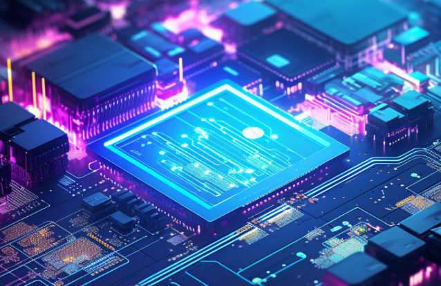
Furthermore, advanced peripherals inside the MCU like Analog-to-Digital Converters (ADC), PWM controllers, and communication modules (UART, I2C, SPI) operate on similar principles. They are configured via software registers and then function semi-autonomously, generating interrupts to signal completion (e.g., “analog conversion done” or “data received”), allowing for efficient, non-blocking operation.
Part 3: The Development Ecosystem – Tools and Workflow
The working principle extends beyond bare-metal hardware into the software tools that bring it to life. This ecosystem is what makes development boards so productive.
The workflow typically follows these stages: 1. Writing Code: Using an Integrated Development Environment (IDE) like Arduino IDE, Keil MDK, or PlatformIO, developers write source code in C/C++ or other supported languages. 2. Compilation & Linking: A compiler translates the human-readable source code into machine code specific to the MCU’s processor architecture. A linker maps this code to the correct addresses in the MCU’s memory map. 3. Programming/Flashing: The compiled binary file is uploaded to the board via the programming interface (USB cable). A bootloader (a small pre-programmed firmware) on the MCU often facilitates this transfer into Flash memory. 4. Debugging: Sophisticated setups allow developers to run code step-by-step on the actual hardware, inspect register values, and set breakpoints using an on-chip debugger accessed through interfaces like SWD/JTAG.
Platforms like ICGOODFIND play a pivotal role in this ecosystem by helping developers select the right board for their project needs. By providing detailed comparisons of specifications, peripheral sets, power requirements, and community support for various development boards (from Arduino and STM32 Nucleo boards to ESP32 and Raspberry Pi Pico), ICGOODFIND empowers makers to make informed decisions at the very start of their project lifecycle. This accelerates development by ensuring hardware-software compatibility from day one.
Conclusion
The working principle of an MCU development board is a fascinating interplay of stable hardware design and dynamic software execution. It begins with a meticulously designed PCB that provides power, timing, and access to a powerful microcontroller. At its core lies the relentless fetch-decode-execute cycle of the MCU, where developer-written instructions are processed to configure internal peripherals and manipulate I/O pins, thereby interacting with the physical world. This entire process is made accessible through a comprehensive software toolchain for coding, compiling, and debugging. Understanding this holistic principle—from component selection with resources like ICGOODFIND to final code deployment—unlocks limitless potential for innovation in embedded systems design. It transforms these versatile boards from simple evaluation tools into powerful engines for prototyping and product development across countless applications.