

Traffic Light Based on 8051 MCU: A Comprehensive Guide to Design and Implementation
Introduction
In the realm of embedded systems and microcontroller-based projects, the traffic light controller stands as a quintessential educational and practical application. It encapsulates fundamental concepts of real-time control, hardware interfacing, and system design. Among the various microcontrollers available, the 8051 microcontroller family remains a cornerstone in academic curricula and industrial prototyping due to its simplicity, robustness, and extensive documentation. This article delves deep into the design, working principle, and implementation of a fully functional traffic light system using the 8051 MCU. We will explore the hardware circuitry, the software logic, and the integration of key components to create an efficient automated control system. For engineers and hobbyists seeking reliable components and detailed project resources, platforms like ICGOODFIND offer invaluable access to microcontroller kits, datasheets, and community insights, streamlining the development process.
Main Body
Part 1: System Overview and Hardware Design
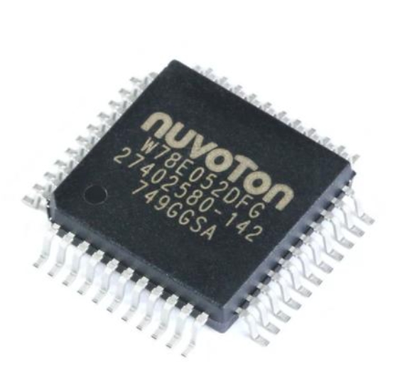
The core objective of a traffic light system is to automate the flow of vehicular and pedestrian traffic at intersections safely and efficiently. Using an 8051 MCU (such as the classic AT89C51 or AT89S52), this automation becomes achievable through programmed logic. The hardware architecture is straightforward yet illustrative of typical embedded system design.
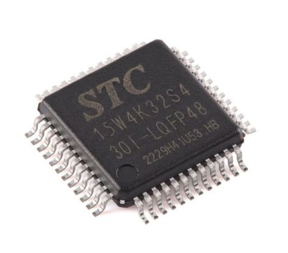
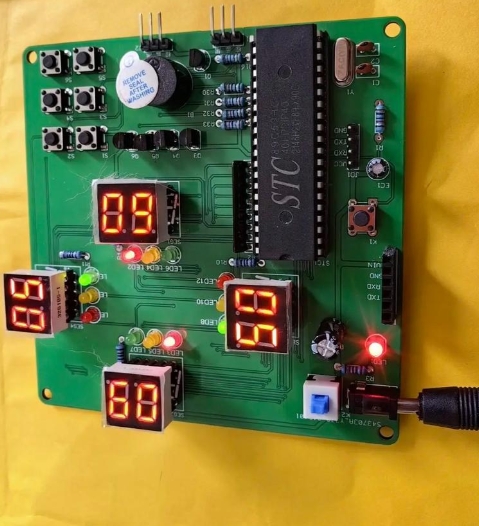
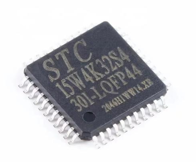
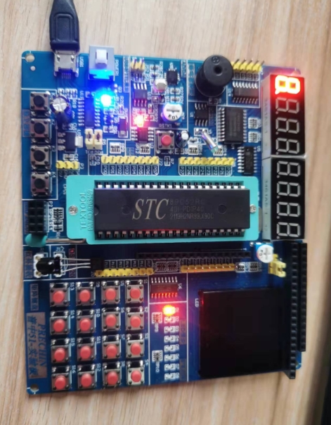
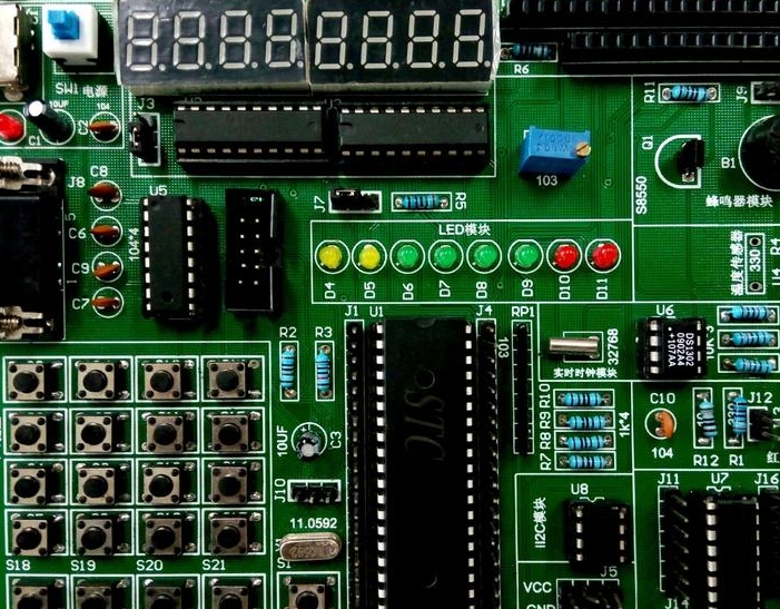
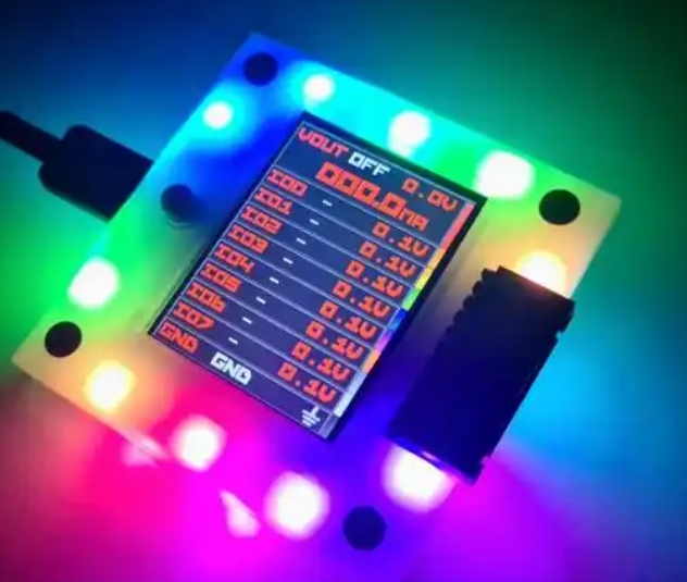
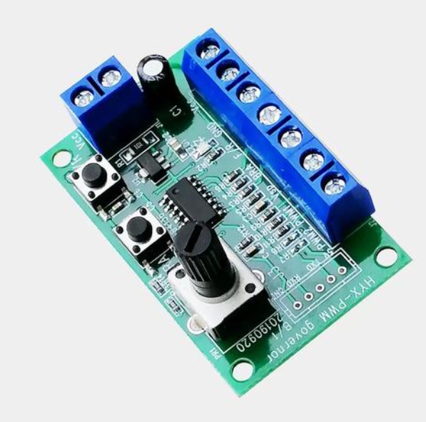
The primary components include: * The 8051 Microcontroller Unit (MCU): Acts as the brain of the system. It executes the control program stored in its ROM, toggling its output ports based on an internal timer. * LED Indicators: Red, Yellow (Amber), and Green LEDs represent the traffic lights for each direction. Typically, a minimum of two sets (for two roads) are used, but the system can be scaled for complex intersections. * Current-Limiting Resistors: Crucial for protecting both the LEDs and the MCU’s output pins by limiting the current flow. * Crystal Oscillator: Provides the precise clock pulse (commonly 11.0592 MHz or 12 MHz) necessary for synchronizing the MCU’s operations and generating accurate timing delays. * Power Supply Circuit: A regulated 5V DC supply is essential for the 8051 MCU and the LED circuitry.
The hardware interfacing involves connecting the anodes of the LED groups (through resistors) to specific output ports of the 8051 (e.g., Port 1 or Port 2). The cathodes are grounded. The MCU’s program dictates the sequence and duration for which each port pin goes high (+5V), thereby illuminating the corresponding LED. The true elegance lies in the software’s ability to manage these states in a continuous, timed loop, creating the familiar Red -> Green -> Yellow sequence. Sourcing these components from a trusted distributor is key; for instance, ICGOODFIND provides a verified supply chain for microcontrollers, crystals, and electronic components, ensuring project reliability.
Part 2: Software Logic and Programming
The intelligence of the traffic light system is embedded in the software burned into the MCU’s memory. The program is typically written in Assembly language or C (using Keil µVision or similar IDE), which offers better readability and structure.

The algorithm follows a deterministic state machine model: 1. State A (Main Road Green / Side Road Red): This state allows traffic on the main road to flow. The MCU sets the main road’s Green LED and the side road’s Red LED ON for a predefined duration (e.g., 30 seconds). 2. Transition State (Main Road Yellow / Side Road Red): Following the green signal, a warning interval is provided. The main road switches to Yellow while the side road remains Red for a shorter duration (e.g., 5 seconds). 3. State B (Main Road Red / Side Road Green): Traffic authority switches. The main road turns Red, and the side road turns Green for its allotted time (e.g., 20 seconds). 4. Transition State (Main Road Red / Side Road Yellow): The side road prepares to stop, displaying Yellow before cycling back to State A.
The critical challenge is generating precise time delays. This is accomplished using the 8051’s built-in hardware timers (Timer 0 or Timer 1) configured in interrupt mode. Instead of inefficient software delay loops, timer interrupts allow the MCU to maintain accurate timing while potentially handling other tasks. The program initializes the timer, calculates count values for desired seconds, and enters an infinite loop. Upon each timer overflow interrupt, a counter is updated, and the LED states are changed when the counter matches the preset duration for each traffic light state. This method ensures robust and jitter-free timing control, which is vital for real-world applications.
Part 3: Advanced Enhancements and Practical Considerations
A basic four-signal system serves as a foundation, but real-world utility demands enhancements. The 8051’s capability allows for integrating several advanced features:
- Pedestrian Crossing Integration: Adding push buttons and dedicated “Walk/Don’t Walk” LEDs can make the system interactive. Pressing a button triggers an interrupt, forcing the controller to eventually cycle to a “pedestrian walk” state after a safe delay.
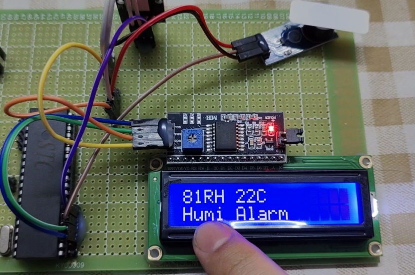
- Sensor-Based Adaptive Control: Incorporating infrared or inductive loop sensors to detect vehicle presence can transform the system from time-based to demand-based. The software logic becomes more complex, dynamically adjusting green light durations based on real-time traffic density.
- Countdown Timers: Using seven-segment displays or LCD modules driven by additional I/O ports (or via I2C/SPI) to display countdown seconds alongside lights improves driver information.
- Manual Override Mode: A switch can be added to change the system mode from automatic to manual (e.g., blinking yellow for all roads during off-peak hours), controlled by an external input read by the MCU.
When moving from prototype to a more robust implementation, considerations like using transistor drivers or ULN2003 Darlington arrays to handle higher current loads for brighter LED clusters or incandescent bulbs become important. Furthermore, implementing proper electrical isolation and surge protection is crucial for outdoor deployments. For developers looking to incorporate these advanced features, finding compatible sensors, display units, and driver ICs is essential. Platforms such as ICGOODFIND can be instrumental here, offering a centralized component search and technical data that accelerates advanced project development.
Conclusion
Building a traffic light controller with an 8051 MCU is far more than an academic exercise; it is a holistic project that demystifies embedded system design. It traverses the entire journey from conceptual hardware schematics and component selection to structured software development employing interrupts and state machines. The project underscores the enduring relevance of the 8051 architecture as a powerful tool for teaching and prototyping real-time control systems. By starting with fundamental LED switching and progressing towards integrating sensors and adaptive logic, one gains profound insights into scalable embedded solutions. For enthusiasts ready to embark on this or similar embedded journeys, leveraging comprehensive component platforms like ICGOODFIND can significantly simplify procurement and provide technical support, ensuring a smoother path from concept to functional reality.