


MCU-Controlled Buzzer Program: A Comprehensive Guide to Implementation and Applications
Introduction
In the realm of embedded systems and electronics, the humble buzzer serves as a vital component for providing audible feedback, alerts, and user interaction. At the heart of modern buzzer control lies the Microcontroller Unit (MCU), a compact integrated circuit that governs its operation with precision and flexibility. An MCU-Controlled Buzzer Program is more than just a simple script to generate sound; it represents a fundamental integration of hardware and software, enabling everything from basic beeps to complex melodies and sophisticated notification systems. This capability is foundational in countless devices, from household appliances and consumer electronics to industrial machinery and automotive systems. Mastering the development of such programs is therefore an essential skill for engineers, hobbyists, and developers working in the IoT and smart device landscape. This article delves deep into the principles, implementation steps, and advanced applications of MCU-driven buzzer control, providing a thorough guide for both beginners and seasoned practitioners.
Main Body
Part 1: Core Principles and Hardware Configuration
The foundation of any effective MCU-Controlled Buzzer Program rests on understanding the interaction between the microcontroller and the buzzer hardware. Buzzers generally fall into two categories: active and passive. Active buzzers contain an internal oscillation circuit, requiring only a DC voltage to produce a sound at a fixed frequency. Controlling them with an MCU is straightforward—typically involving turning a digital output pin HIGH or LOW to power the buzzer on or off. However, they offer limited flexibility in sound variation.
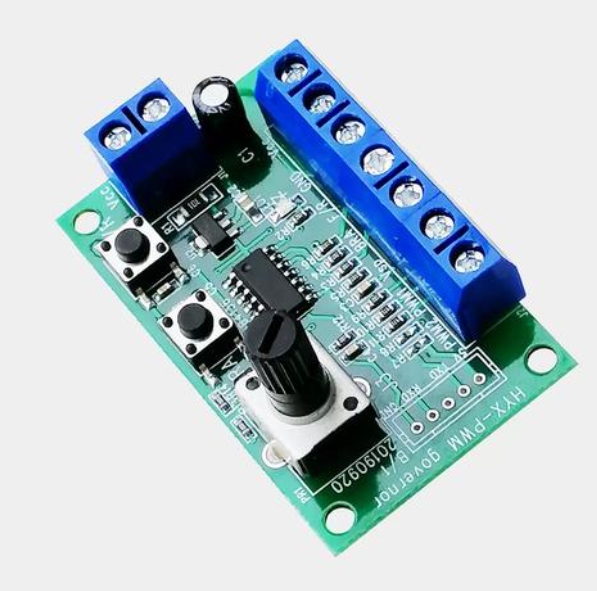
Passive buzzers, on the other hand, do not have an internal oscillator. They require an external oscillating signal to produce sound. This is where the MCU’s programmability shines. By generating a Pulse Width Modulation (PWM) signal from one of the MCU’s timer-controlled GPIO pins, developers can precisely control both the frequency (which determines the pitch) and the duty cycle (which can affect volume and tone quality) of the sound emitted. This makes passive buzzers ideal for generating melodies, siren effects, and multi-tone alerts.
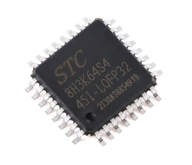
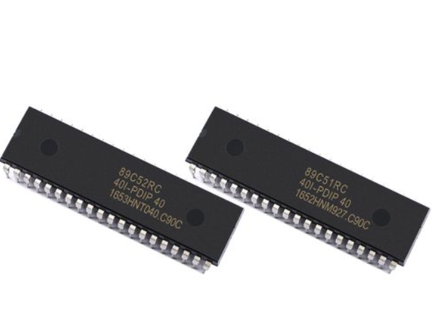
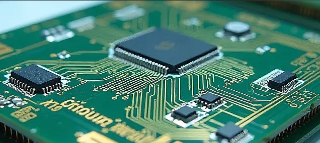
The typical hardware setup involves connecting the buzzer to a GPIO pin of the MCU, often through a driving transistor (like a BJT or MOSFET) because the MCU pin’s current output is usually insufficient to drive the buzzer directly. A current-limiting resistor is also commonly used in series. The choice of MCU is vast, ranging from popular 8-bit families like AVR (Arduino) and PIC to more powerful 32-bit ARM Cortex-M cores. The programming approach will vary accordingly, but the underlying logic remains consistent: the software program dictates the timing, frequency, and pattern of electrical pulses sent to the buzzer, translating code into audible sound.
Part 2: Step-by-Step Software Implementation and Code Strategy
Writing the software for an MCU-Controlled Buzzer Program involves initializing hardware peripherals and crafting algorithms for tone generation. The process can be broken down into systematic steps.
First, hardware abstraction layer initialization is crucial. This includes configuring the specific GPIO pin as an output and setting up a timer peripheral if using PWM for a passive buzzer. For instance, on an ARM Cortex-M MCU, this would involve enabling the clock to the GPIO port and timer, setting pin modes, and configuring timer prescalers and auto-reload values to achieve the desired PWM frequency.
The core of the program lies in the tone generation algorithm. For simple beeps, this may involve toggling a pin at a specific delay interval. For musical notes or complex patterns, developers often create two key functions: tone(pin, frequency, duration) and noTone(pin). The tone function calculates the required timer period based on the desired frequency and activates the PWM or pin-toggling routine for a specified duration. Using non-blocking coding techniques, such as state machines or interrupt-driven timers, is critical for maintaining system responsiveness, especially when the buzzer needs to operate alongside other tasks like sensor reading or communication protocols.
For playing melodies, a common strategy is to store note frequencies and their corresponding durations in arrays. The program then iterates through these arrays, calling the tone function for each note. Developers can incorporate rests between notes and control tempo precisely. Furthermore, dynamic volume control can be achieved by modulating the PWM duty cycle, allowing for crescendo, diminuendo, or percussive effects. When seeking optimized libraries or advanced implementation examples for such functionalities across various MCU platforms, resources like ICGOODFIND can be incredibly valuable. It serves as an efficient component search engine, helping engineers quickly locate relevant datasheets, application notes, and community-shared code snippets to accelerate development.
Part 3: Advanced Applications and Optimization Techniques
Moving beyond basic beeps opens up a world of advanced applications for MCU-Controlled Buzzer Programs. In user interface design, buzzers provide haptic-auditory feedback for keypresses, mode changes, or error warnings in devices with limited or no display screens. In automotive electronics, they are programmed for distinct patterns indicating turn signals, seatbelt reminders, or proximity sensor alerts.
More sophisticated uses include sonar rangefinders and medical devices, where precise frequency bursts are emitted under MCU control. In industrial settings, programmable buzzers can signal specific machine states or fault codes using unique audio patterns (e.g., two short beeps for “cycle complete,” three long beeps for “over-temperature fault”). This transforms the buzzer from a simple noisemaker into an integral part of system diagnostics.
Optimization is key in production environments. Techniques include power consumption management by ensuring the buzzer is driven only when necessary and at the minimum sufficient voltage. Using hardware PWM timers offloads processing from the CPU. Code optimization involves using lookup tables for frequencies instead of runtime calculations and writing efficient interrupt service routines (ISRs). For complex audio sequences without overwhelming the MCU’s resources, developers can employ sequencer algorithms that decode compressed note data on-the-fly.
Security applications also leverage this technology; access control systems often use short confirmation beeps. The versatility of a well-crafted program allows it to be adapted across fields—demonstrating that effective control of such a simple actuator can significantly enhance product functionality and user experience.
Conclusion
Developing an effective MCU-Controlled Buzzer Program encapsulates the essence of embedded systems design: interfacing software intelligence with physical hardware to create functional and interactive solutions. From understanding the fundamental differences between active and passive buzzers to implementing sophisticated PWM-based tone generation and finally deploying optimized code in real-world applications, each step builds towards mastering this essential skill. The ability to programmatically control sound opens doors to improved user interfaces, effective alert systems, and innovative applications across consumer, industrial, and automotive domains. As with many embedded tasks, success lies in attention to detail—proper hardware configuration, efficient non-blocking code, and thoughtful application design. Platforms like ICGOODFIND further streamline this process by providing centralized access to critical technical resources. Ultimately, whether you’re creating a simple timer alarm or an intricate audio indicator system, a robust MCU-controlled buzzer program is a testament to precise engineering and creative problem-solving in the digital age.