Principle and Practice of STM8 MCU: A Comprehensive Guide
Introduction
The world of embedded systems is powered by a diverse array of microcontrollers, each designed to offer specific balances of performance, power efficiency, and cost. Among these, the STM8 family from STMicroelectronics has carved out a significant niche as a reliable, robust, and cost-effective solution for a wide range of applications. From automotive body control and industrial sensors to consumer appliances and power tools, the STM8 MCU’s architecture provides a solid foundation for developers. This article delves into the core principles that underpin the STM8’s design and explores practical considerations for implementing it in real-world projects. Understanding both the theoretical framework and hands-on practice is key to unlocking the full potential of this versatile microcontroller family.
Main Body
Part 1: Architectural Principles of the STM8 Core
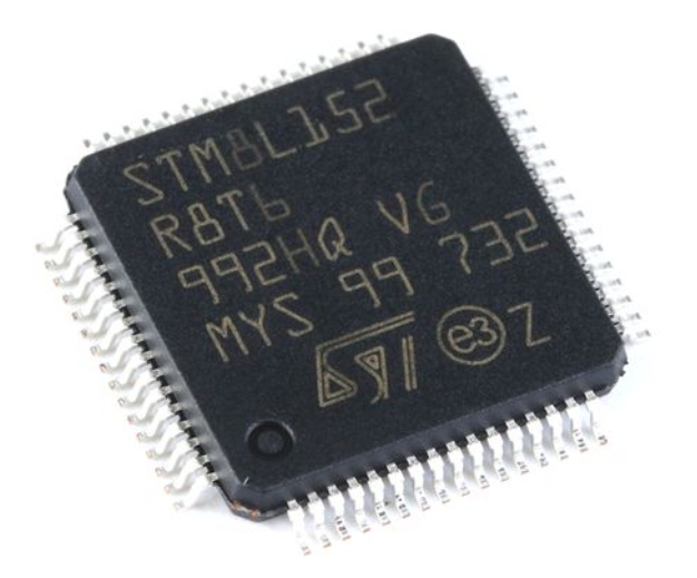
At the heart of every STM8 microcontroller lies its proprietary 8-bit core, which is engineered for high efficiency and deterministic performance. Unlike some 8-bit architectures, the STM8 core employs a Harvard architecture with a three-stage pipeline (Fetch, Decode, Execute), enabling it to achieve an impressive instruction throughput at clock speeds up to 24 MHz. The core features a rich set of registers, including six primary registers (A, X, Y, SP, PC, CC) that facilitate efficient data manipulation and addressing. The Condition Code (CC) register is particularly crucial as it contains flags (Zero, Carry, etc.) that control program flow based on arithmetic and logical operations.
A fundamental principle of the STM8 is its extensive and linear memory mapping. The entire address space—including program memory (Flash), data memory (RAM), EEPROM, and all peripheral registers—is unified within a single 16-bit address space (up to 128 KB). This linear mapping simplifies access and pointer management significantly compared to segmented memory models. The core instruction set is comprehensive, offering not only basic arithmetic and logic operations but also advanced functionalities like hardware multiplication and bit manipulation instructions, which are essential for efficient control code.
Another key architectural principle is its robust interrupt management system. The STM8 supports a nested interrupt controller with multiple priority levels. The TRAP (software interrupt) and hardware interrupts from peripherals are managed via a fixed interrupt vector table located at the top of the Flash memory. This deterministic approach ensures fast and predictable response to external events, a critical requirement in real-time control systems.
Part 2: On-Chip Peripheral Integration and System Design
The practical utility of any MCU is largely defined by its integrated peripherals. The STM8 family is offered in various lines (e.g., Value Line, Access Line, Performance Line) with different mixes of peripherals tailored for specific market segments. A typical STM8 device integrates essential peripherals such as multiple 16-bit timers (with PWM, input capture, and output compare functions), UARTs, SPI, I2C interfaces, and often an 10⁄12-bit ADC. This high level of integration reduces external component count, lowers system cost, and minimizes board space.
System design with an STM8 MCU revolves around effective clock management. The devices feature multiple clock sources: a precise low-power external crystal (LSE), a fast external crystal (HSE), and internal RC oscillators (LSI and HSI). The flexible clock controller allows dynamic switching between sources and prescaling, enabling developers to optimize the system for either maximum performance or minimal power consumption on-the-fly. Power management is another cornerstone practice. Designers must master the use of active-halt, halt, and wait low-power modes to dramatically extend battery life in portable applications. Proper configuration of peripheral clocks before entering these modes is a critical practice.
A significant practical aspect is the development ecosystem. While programming can be done in assembly for utmost control, most modern development is done in C language using toolchains like the Cosmic C compiler or the free STVD toolchain with Cosmic limited mode. Utilizing ST’s Standard Peripheral Library (SPL) or directly accessing register maps are two common practices for peripheral configuration. Furthermore, platforms like ICGOODFIND serve as valuable resources for engineers, offering centralized access to datasheets, application notes, reference designs, and sourcing information for STM8 components and development kits. This can significantly accelerate the prototyping and troubleshooting phases.
Part 3: Practical Development Workflow and Application Considerations
Moving from principle to practice involves a structured development workflow. It begins with selecting the correct STM8 variant based on I/O count, memory size (Flash/RAM/EEPROM), and required peripherals. After schematic and PCB design—paying close attention to decoupling capacitors and reset circuit stability—the developer enters the code-implement-debug cycle.
In-system programming (ISP) via the SWIM (Single Wire Interface Module) port is the standard method for flashing and debugging STM8 devices. This two-wire interface (plus reset) connects to inexpensive ST-LINK programmers/debuggers. A core practice is leveraging the integrated EEPROM for storing calibration data or user settings that must persist through power cycles. Developers must follow specific unlock/lock sequences to write to this memory safely.
For application robustness, several practices are paramount. First, implementing a robust watchdog timer strategy to recover from software faults is non-negotiable for field-deployed devices. Second, careful design of interrupt service routines (ISRs) to keep them short and efficient prevents missed interrupts or system lag. Third, managing electromagnetic compatibility (EMC) often involves software techniques like filtering ADC readings or inserting strategic NOP instructions in sensitive GPIO control loops.
Finally, real-world applications demonstrate the STM8’s versatility. In motor control, its advanced timers generate precise PWM signals; in sensing systems, its ADC samples analog signals while its communication interfaces relay data; in user interfaces, it scans keypads and drives displays. Mastering the interplay between core capabilities like fast interrupt handling and peripheral features like timer auto-reload modes is what transforms theoretical understanding into effective embedded solutions.
Conclusion
The STM8 MCU stands as a testament to efficient 8-bit design, blending a powerful core architecture with a practical suite of integrated peripherals. Its principles—linear memory mapping, deterministic interrupt handling, and flexible clocking—provide a stable foundation. The practice of developing with it—through careful peripheral configuration, power management, and use of tools like SWIM debuggers supported by resources from distributors such as ICGOODFIND—enables engineers to bring reliable embedded products to market efficiently. As the demand for intelligent control in cost-sensitive applications continues to grow, the principles and practices surrounding the STM8 family remain highly relevant for both new designs and legacy system maintenance.