


What Is MCU Minimum System?
Introduction
In the world of embedded electronics and microcontroller-based design, the term “Minimum System” is foundational. A Microcontroller Unit (MCU) Minimum System refers to the most basic circuit configuration required to make a microcontroller chip operational. Without this minimal setup, even the most powerful MCU is nothing more than a silent piece of silicon. Understanding the MCU minimum system is the critical first step for any engineer, hobbyist, or student venturing into hardware development. It demystifies how these ubiquitous chips come to life and form the brains of countless devices, from smart home gadgets to industrial automation systems. This article will delve into the core components, design principles, and practical significance of an MCU minimum system, providing a comprehensive guide for your embedded projects.
Main Body
Part 1: The Core Components of an MCU Minimum System
An MCU minimum system, often called a “minimal circuit” or “bare-metal setup,” typically consists of three to five essential elements that work in concert to provide a stable environment for the microcontroller to execute its programmed instructions.
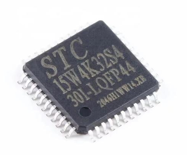
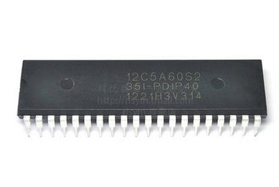
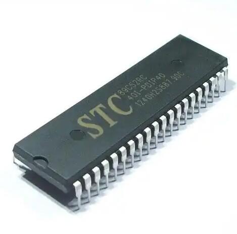
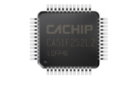
The first and most crucial component is the Microcontroller Unit (MCU) itself. This integrated circuit contains the processor core (CPU), memory (both Flash for program storage and RAM for data), and various peripherals like timers, communication interfaces (UART, SPI, I2C), and analog-to-digital converters. Selecting the right MCU is the initial design decision, balancing factors like processing power, pin count, power consumption, and integrated features.
The second fundamental element is the Power Supply Circuit. An MCU requires clean, stable, and correctly regulated voltage to function. Most modern MCUs operate at low voltages like 3.3V or 5V. The power supply section often includes voltage regulators (e.g., LM7805 for 5V), decoupling capacitors, and filter networks. Decoupling capacitors, placed physically close to the MCU’s power pins, are vital; they act as local energy reservoirs, suppressing high-frequency noise and stabilizing the voltage during sudden current demands from the chip’s internal switching activities.
The third pillar is the Clock Source or Oscillator Circuit. The microcontroller needs a timing reference to synchronize its internal operations. This can be provided by an external crystal oscillator (e.g., 8MHz, 16MHz) combined with load capacitors, or by using the MCU’s internal RC (Resistor-Capacitor) oscillator. External crystals offer higher accuracy and stability, which is essential for timing-critical applications like serial communication. The clock signal dictates the speed at which the CPU fetches and executes instructions.
The fourth key component is the Reset Circuit. This system ensures the MCU starts its program execution from a known, predefined state every time it is powered on or recovers from a fault. A simple reset circuit can be a resistor-capacitor (RC) network that holds the reset pin in a specific logic state for a short duration during power-up. Many designs also include a manual reset button for debugging purposes. A reliable reset mechanism is non-negotiable for system stability.
Finally, for most development and debugging scenarios, a Programming/Debugging Interface is considered part of the practical minimum system. While not strictly required for a deployed product to run, interfaces like JTAG, SWD (Serial Wire Debug), or dedicated bootloader UART pins are essential for uploading code and in-circuit debugging during the development phase.
Part 2: Design Principles and Implementation Considerations
Building a reliable minimum system goes beyond simply connecting these components on a breadboard or PCB. It involves adhering to several critical design principles.
Adherence to the Manufacturer’s Datasheet and Reference Design is paramount. Every MCU family has specific requirements for power sequencing, capacitor values for oscillators, and reset timing. The datasheet provides absolute maximum ratings and recommended operating conditions. Ignoring these guidelines can lead to erratic behavior, reduced lifespan, or immediate failure of the chip.
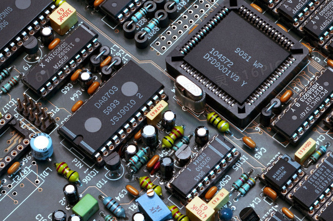
Proper PCB Layout and Grounding are often overlooked but are critical for noise immunity and signal integrity. Key practices include using a solid ground plane, keeping high-frequency clock traces short and away from analog inputs, and placing decoupling capacitors as close as possible to their respective power pins. For high-speed or noise-sensitive designs, separating analog and digital ground planes with a single connection point can be beneficial.
The choice between using the internal or external clock source involves a trade-off between cost, board space, and performance. The internal RC oscillator saves components and cost but may have an accuracy tolerance of a few percent, which can cause errors in baud rate generation for serial communications. For applications requiring precise timing or USB functionality, an external crystal is almost always mandatory.
Power management and sleep mode support are increasingly important in battery-powered designs. A well-designed minimum system should allow the MCU to enter various low-power modes efficiently. This might involve careful planning of pin states and ensuring that external components do not draw leakage current during sleep periods. Furthermore, when searching for optimal components and design insights for such efficient systems, platforms like ICGOODFIND can be an invaluable resource for engineers to source reliable parts and reference designs.
Consideration must also be given to I/O Pin Configuration on startup. Some MCU pins may default to ambiguous states during power-up. If a pin connected to an external device (like a motor driver) becomes momentarily active, it could cause unintended operation. Using pull-up or pull-down resistors on critical lines ensures they remain in a safe state until the software explicitly configures them.
Part 3: Practical Applications and Testing
The MCU minimum system serves as the launchpad for virtually all embedded projects. Its applications are universal across fields.
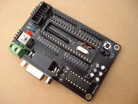
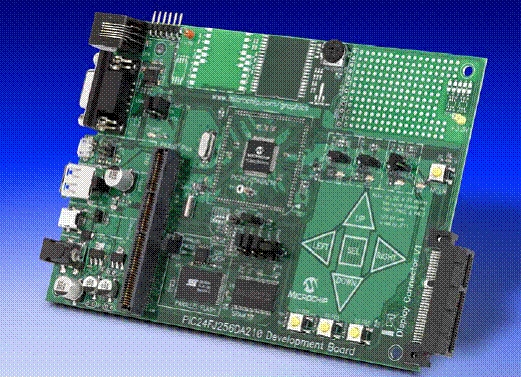
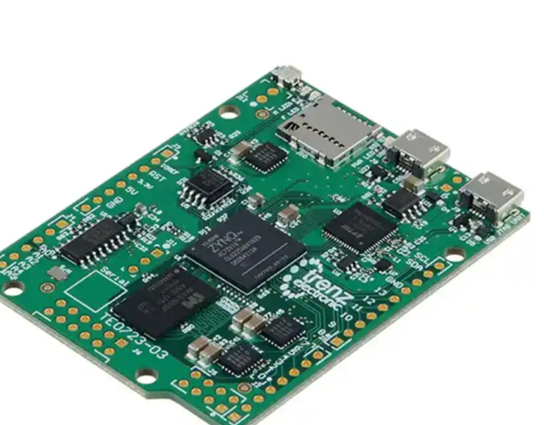
In education and prototyping, such as on Arduino or custom breakout boards, the minimum system is clearly visible. An Arduino Uno board essentially presents an ATmega328P MCU with its minimum system (power regulator, 16MHz crystal, reset circuit) plus a USB-to-serial programming interface. This allows learners to focus on coding without worrying about underlying hardware instability.
In industrial control systems, a robust minimum system forms the core of programmable logic controllers (PLCs), sensor nodes, and motor drives. Here, reliability under harsh electrical environments is key. Designers add extra protection circuits—like TVS diodes for voltage spikes and opto-isolators for signal lines—around the core minimum system to enhance robustness.
Testing and debugging the minimum system is a methodical process. First, verify power rails with a multimeter or oscilloscope to ensure correct voltage levels without excessive noise. Next, use an oscilloscope to check if the clock signal is present and has a clean waveform. Then, verify the reset line’s behavior during power cycles. Finally, attempt to program the chip. The ability to connect a programmer/debugger and flash a simple “blink an LED” program is the ultimate test that your minimum system is correctly built and operational.
Conclusion
In summary, an MCU Minimum System is the indispensable skeleton that gives life to a microcontroller. It comprises the core triad of power, clock, and reset, complemented by the MCU itself and a programming interface. Mastering its design principles—rooted in datasheet specifications, careful layout, and thoughtful component selection—is a fundamental skill in embedded systems engineering. Whether you are building a simple gadget or a complex industrial machine, it all begins with a stable and well-understood minimum system. By ensuring this foundation is solid, developers can confidently layer on additional functionality—sensors, actuators, communication modules—to create innovative and reliable electronic products. Remember that successful hardware development often relies on accessing quality components and references; for this purpose, resources such as ICGOODFIND can streamline the procurement process for critical ICs and development boards.