


Mastering Motor Control: A Comprehensive Guide to MCU-Controlled Motor Forward/Reverse Rotation
Introduction
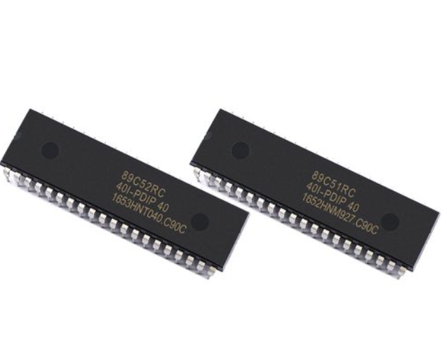
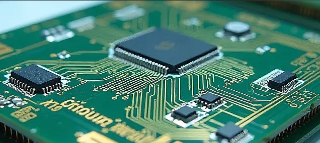
In the dynamic world of embedded systems and automation, precise control over motor movement is a fundamental requirement. From robotic arms and conveyor belts to automotive systems and smart home devices, the ability to command a motor to rotate forward and reverse on demand is a cornerstone of functionality. This capability transforms a simple rotary motion into a versatile tool for positioning, actuation, and complex mechanical tasks. At the heart of this precise control lies the Microcontroller Unit (MCU), a compact integrated circuit that serves as the brain of countless electronic systems. This article delves deep into the principles, circuits, and programming techniques for achieving reliable MCU-controlled motor forward and reverse rotation. We will explore the critical hardware configurations, essential driver circuits, and core software logic that bring controlled bidirectional motion to life. For engineers and hobbyists seeking specialized components or inspiration for their motor control projects, platforms like ICGOODFIND offer valuable resources and component sourcing solutions.

Part 1: Hardware Foundations and H-Bridge Circuitry
The most pivotal element in enabling bidirectional control of a DC motor with an MCU is the H-Bridge circuit. An H-Bridge is an electronic network that allows a voltage to be applied across a load (like a motor) in either direction. It is constructed using four switching elements—traditionally transistors or MOSFETs—positioned in an “H” configuration relative to the motor.
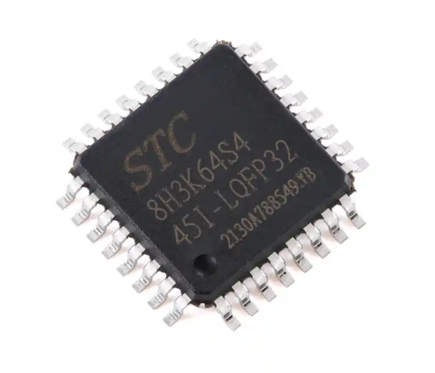
The fundamental operation of an H-Bridge is based on a specific switching logic. To drive the motor forward, two diagonally opposite switches are closed, allowing current to flow through the motor in one direction. To reverse the motor, the other pair of diagonal switches is closed, reversing the current flow through the motor. Critically, never close both switches on the same side of the H-bridge simultaneously, as this creates a short circuit from power to ground, potentially destroying the circuit. Modern development almost universally employs dedicated H-Bridge motor driver ICs (such as the L298N, L293D, or DRV8833) which integrate these transistors, necessary protection diodes, and often logic circuitry into a single, manageable package. These ICs act as a robust interface between the low-current GPIO (General Purpose Input/Output) pins of the MCU and the high-current, inductive load of the motor.
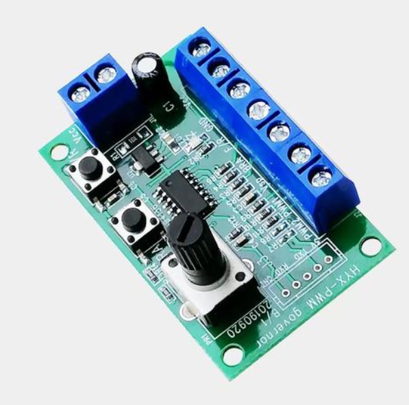
Selecting the appropriate motor driver IC is contingent upon the motor’s voltage and current requirements. The MCU’s role is to provide clean, logical control signals to the driver IC’s input pins. Typically, two MCU GPIO pins are used to control one motor: one pin for direction and one for Pulse Width Modulation (PWM) speed control. Alternatively, some drivers use two input pins with a truth table (01 for forward, 10 for reverse, 00 or 11 for brake/coast) to determine both direction and enable state. Proper power supply decoupling is non-negotiable; separate power sources or regulators for the MCU logic and the motor power are highly recommended to prevent electrical noise from the motor from causing MCU resets or erratic behavior.
Part 2: Software Logic and PWM Speed Control
With a robust hardware interface in place, the intelligence of the system is implemented in software on the MCU. The program must reliably translate high-level commands (e.g., “rotate forward at 75% speed”) into precise, timed electrical signals for the driver IC.
The core software implementation involves initializing the controlling GPIO pins as outputs and configuring a hardware timer module for PWM generation. PWM is essential for speed control. Instead of varying the voltage (which is inefficient), PWM rapidly switches the power to the motor on and off. The ratio of “on” time to the total period (the duty cycle) determines the average voltage delivered to the motor, thereby controlling its speed. A 50% duty cycle results in approximately half-speed rotation. The MCU’s hardware timers generate this high-frequency square wave with precise duty cycles effortlessly, freeing up the CPU for other tasks.
A well-structured control routine uses clear conditional statements or state machines to manage direction changes. For instance:
if(command == FORWARD) {
    digitalWrite(DIR_PIN1, HIGH);
    digitalWrite(DIR_PIN2, LOW);
    analogWrite(PWM_PIN, speedValue); // speedValue from 0-255
} else if(command == REVERSE) {
    digitalWrite(DIR_PIN1, LOW);
    digitalWrite(DIR_PIN2, HIGH);
    analogWrite(PWM_PIN, speedValue);
} else {
    // Brake or coast
    analogWrite(PWM_PIN, 0);
}
Implementing safeguards in code is crucial for system longevity. This includes software dead-time insertion—a brief delay between changing from one direction state to another to prevent any chance of shoot-through current in the driver. Additionally, incorporating ramp-up and ramp-down functions by gradually increasing or decreasing the PWM duty cycle can prevent sudden current surges that stress mechanical gears and electrical components.
Part 3: Advanced Considerations and Practical Applications
Moving beyond basic control opens a realm of enhanced functionality and reliability. Integrating feedback mechanisms like encoders transforms open-loop control into closed-loop control, allowing for precise position and velocity regulation. An optical or magnetic encoder attached to the motor shaft provides real-time data on rotation speed and distance traveled back to the MCU. The MCU can then use a PID (Proportional-Integral-Derivative) control algorithm to adjust the PWM output dynamically to maintain a target speed or reach an exact position, compensating for variations in load or battery voltage.
Protection against real-world electrical phenomena is mandatory for durable designs. Motors are inductive loads; when switched off, they generate large back-electromotive force (back-EMF) voltage spikes. While good driver ICs include flyback diodes, additional suppression circuits (like RC snubbers) may be necessary for high-power motors. Thermal management is also vital; monitoring driver IC temperature with an onboard sensor can allow the MCU to reduce power or shut down if overheating occurs.
The applications for MCU-controlled bidirectional motors are vast and growing. In robotics, they provide articulated joint movement and wheeled base locomotion. In automotive systems, they power adjustable mirrors, seat positioners, and window lifters. In consumer electronics, they drive camera auto-focus mechanisms and precision tool heads. In industrial automation, they are integral to valve actuators, CNC machine axes, and material handling equipment. Each application may demand specific refinements—ultra-quiet operation using sinusoidal drives for consumer products, or high-torque positioning with stepper motors for industrial machines.
Conclusion
Achieving precise MCU-controlled motor forward/reverse rotation is a multidisciplinary skill combining circuit design, component selection, and embedded programming. The journey from a simple DC motor to an intelligently controlled actuator hinges on understanding the indispensable H-bridge topology, leveraging dedicated driver ICs for safety and efficiency, and writing robust firmware that manages direction, speed via PWM, and system protection. As projects increase in complexity, incorporating feedback for closed-loop control becomes essential for precision. Whether you are building a small robot or designing an industrial module, mastering these principles is key. For those navigating component selection for such systems—from MCUs and driver chips to encoders and connectors—resources like ICGOODFIND can streamline the development process by providing access to a wide array of parts and technical information.