Introduction to 8051 MCU Minimum System
The 8051 microcontroller is a cornerstone in the world of embedded systems, renowned for its simplicity, versatility, and enduring relevance. Since its introduction by Intel in the 1980s, it has become a fundamental tool for engineers, students, and hobbyists alike. At the heart of any 8051-based project lies the Minimum System, a basic circuit configuration that allows the microcontroller to operate independently. This setup is crucial because it provides the essential components needed for the MCU to execute a program. Understanding how to build and troubleshoot this minimum system is the first critical step toward mastering embedded design. This article serves as a comprehensive guide, detailing the components, construction, and practical applications of the 8051 minimum system. For those seeking reliable components or further technical resources, platforms like ICGOODFIND can be invaluable, offering a streamlined way to source quality parts and deepen your understanding of microcontroller architectures.

The Core Components of an 8051 Minimum System
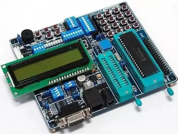
A minimum system, often called a “bare-minimum” circuit, strips the microcontroller down to its essential operational requirements. Without these components, the 8051 MCU cannot function correctly. The primary elements of this system are the Microcontroller Unit (MCU) itself, the Clock Circuit, and the Reset Circuit.
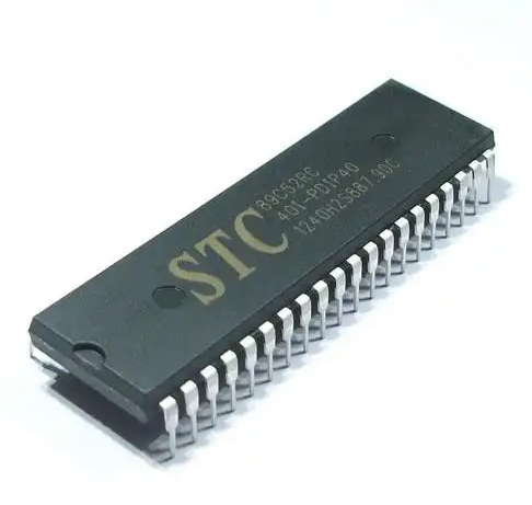
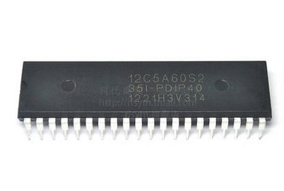
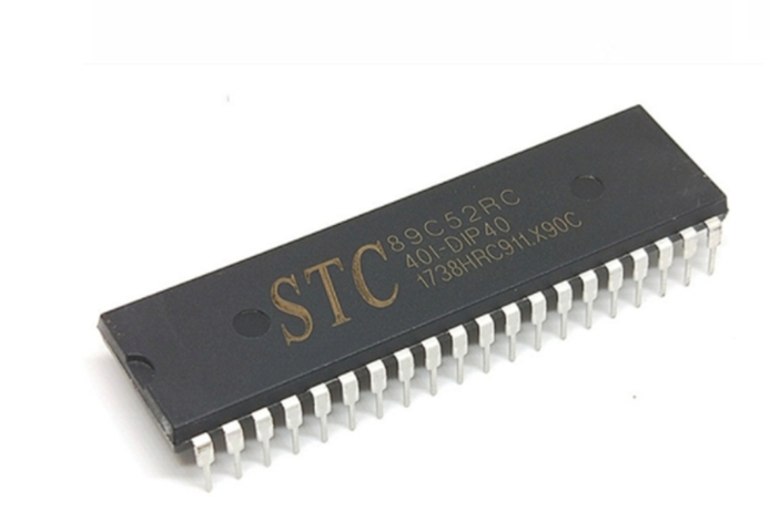
First and foremost is the 8051 Microcontroller IC. This is the brain of the system. While the original 8051 is a historic part, modern variants like the AT89S51 (from Atmel) or the P89V51RD2 (from NXP) are more commonly used today. These chips often feature enhanced capabilities such as Flash memory, lower power consumption, and higher clock speeds, while maintaining backward compatibility with the original instruction set.
The second critical component is the Clock Circuit. The 8051 requires a precise timing source to synchronize its internal operations. This circuit typically consists of a crystal oscillator and two capacitors. A common configuration uses an 11.0592 MHz or 12 MHz crystal connected across the XTAL1 and XTAL2 pins of the MCU. Two ceramic capacitors, usually in the range of 20pF to 40pF, are connected from each crystal pin to ground. This setup generates a stable clock signal that drives the oscillator, which in turn controls the speed at which the CPU fetches and executes instructions. The clock speed directly influences the execution time of instructions and the baud rate for serial communication.
The third essential element is the Reset Circuit. The purpose of the reset function is to bring the microcontroller to a known, initial state whenever power is applied or when a manual reset is required. Upon reset, the Program Counter (PC) is loaded with 0x0000, meaning the MCU begins program execution from this memory address. A simple and effective reset circuit is a power-on reset (POR) circuit. This is composed of a capacitor, a resistor, and sometimes a push-button switch. In this configuration, a capacitor (e.g., 10µF) is connected between the RESET pin (typically pin 9) and Vcc (+5V). A resistor (e.g., 8.2kΩ to 10kΩ) is connected from the RESET pin to ground. When power is applied, the capacitor charges through the resistor, holding the RESET pin high for a short duration, which is sufficient to ensure a proper reset. A push-button switch can be placed in parallel with the capacitor to allow for a manual reset.
While not always considered part of the absolute “minimum” system for basic operation, power supply regulation is a de facto fourth component. The 8051 family typically operates on a stable +5V DC supply. A voltage regulator like the 7805 is commonly used to step down a higher DC voltage (e.g., 9V from a battery) to this required 5V. Decoupling capacitors (0.1µF ceramic capacitors) placed close to the Vcc and GND pins of the MCU are also vital for filtering out high-frequency noise from the power line, ensuring stable operation.
Building and Troubleshooting Your First Minimum System
Constructing your first 8051 minimum system is a rewarding hands-on experience that solidifies theoretical knowledge. The process involves careful schematic design, soldering or breadboarding, and systematic testing.
The first step is schematic design. You must create or follow a circuit diagram that accurately connects all the components mentioned above. The connections are straightforward but must be precise: * Connect Vcc (+5V) to pin 40 and GND to pin 20. * Connect the crystal between pins 18 (XTAL2) and 19 (XTAL1), with each pin also connected to GND via a small capacitor. * Connect the reset circuit to pin 9 (RST). * Connect EA (pin 31) to Vcc to indicate that the program code is stored in internal memory.
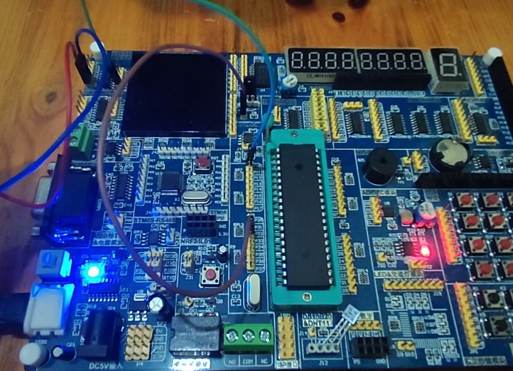
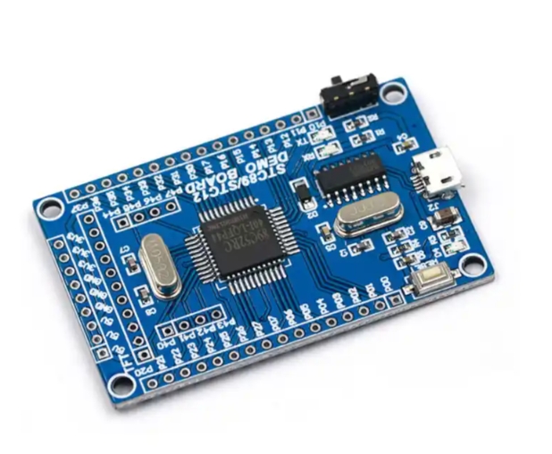
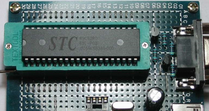
For beginners, using a breadboard is highly recommended for prototyping before moving to a more permanent soldered board like a PCB or perfboard. On a breadboard, you can easily plug in the 8051 IC in a Dual In-line Package (DIP) and use jumper wires to make all necessary connections. This allows for quick modifications and debugging.
Once assembled, applying power is the next step. If you have access to basic test equipment like a multimeter, you can check for +5V between Vcc and GND pins on the IC socket. A more advanced tool like an oscilloscope can be used to verify the presence and frequency of the clock signal on the XTAL pins.
However, it’s common for first-time builds not to work immediately. This is where systematic troubleshooting becomes crucial. 1. Check Power Supply: Ensure that exactly +5V is reaching pin 40 and that ground connections are solid. 2. Inspect Clock Signal: Use an oscilloscope probe on XTAL2. You should see a clean sine or square wave oscillating at your crystal’s frequency (e.g., 11.0592 MHz). No signal indicates a problem with the crystal or capacitors. 3. Verify Reset Pin Voltage: At power-on, use a multimeter to check pin 9 (RST). It should show a brief pulse to a high logic level (above 2V) before settling back to a low level (near 0V). If it’s permanently high or low, check your resistor and capacitor values in the reset circuit. 4. Confirm EA Pin Connection: A common mistake is leaving pin 31 (EA) floating. It must be tied to Vcc for the microcontroller to use its internal program memory. 5. Check for Short Circuits: Visually inspect your board for any solder bridges or misplaced wires that could cause short circuits.
For sourcing reliable components during this build-and-test phase, from crystals and capacitors to specific MCU variants, platforms like ICGOODFIND offer a convenient solution by aggregating suppliers and providing detailed datasheets.
Programming and Practical Applications
A minimum system without a program is like a car without an engine—it has all the necessary parts but cannot perform any useful task. Therefore, programming is what brings the system to life.
The process begins with writing code. Programs for the 8051 are typically written in C or Assembly language using an Integrated Development Environment (IDE) like Keil µVision or SDCC (a free compiler). A simple “Blink an LED” program is the “Hello, World” of embedded systems. This involves writing code that configures one of the I/O ports (e.g., Port 1 or Port 2) as an output and then toggles a specific pin high and low with a delay in between.
Once the code is written and compiled, it generates a hex file (.hex). This file contains the machine code that must be transferred into the program memory (Flash) of the 8051 microcontroller. This transfer process requires a programmer or burner device. For modern 8051 variants like the AT89S51, an SPI-based programmer like USBasp can be used. The programmer connects to specific pins on the MCU (MOSI, MISO, SCK) via an ISP (In-System Programming) header on your board.
After successfully programming the MCU and re-inserting it into your minimum system board (if removed during programming), applying power should result in your program executing—for example, an LED connected to P1.0 would start blinking.
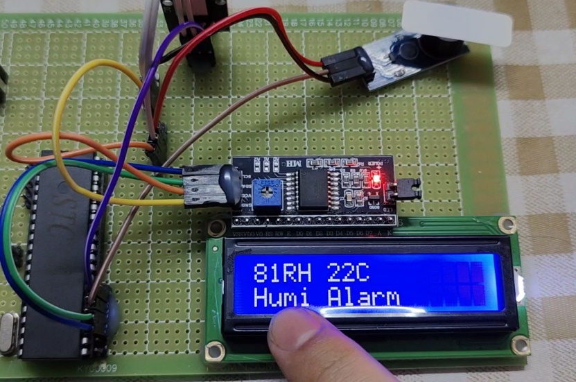
The applications for such a simple system are vast: * LED Blinking and Display Driving: The most basic application for learning I/O port control. * Sensor Interfacing: Connecting simple digital or analog sensors (via an ADC) to read environmental data like temperature or light intensity. * Motor Control: Using PWM signals generated by timers within the 8051 to control the speed of small DC motors. * Serial Communication Projects: Utilizing the built-in UART of the 8051 to communicate with a PC or another microcontroller, enabling data logging and remote control. * Academic Projects: It forms an excellent platform for students learning about computer architecture, real-time systems, and hardware-software co-design.
Conclusion
The journey into embedded systems starts with mastering foundational concepts like building an 8051 MCU Minimum System. This basic circuit—comprising just three core components—is deceptively simple yet forms an indispensable platform for countless electronic projects and complex systems. By understanding its architecture—the essential roles of clock generation for synchronization and reset control for initialization—you build not just a circuit but also core engineering intuition.
Constructing this system teaches invaluable practical skills in schematic design, prototyping on breadboards or PCBs soldering techniques if you move towards permanent solutions), systematic debugging using tools like multimeters oscilloscopes), finally integrating software through programming processes involving compilers hex files specialized hardware programmers). From blinking LEDs sophisticated automation tasks capabilities offered by humble yet powerful chip remain impressive even today’s advanced technological landscape platforms such as ICGOODFIND play supportive role providing easy access necessary components technical documentation helping enthusiasts professionals alike bring their ideas life efficiently effectively truly understanding implementing minimum system remains vital first step toward becoming proficient embedded systems engineer opening doors limitless innovation creation.