


Traffic Light Design Based on 8051 MCU: A Comprehensive Guide to Embedded System Implementation
Introduction
In the realm of embedded systems and microcontroller applications, few projects are as iconic and educationally rich as designing a traffic light control system. The Traffic Light Design Based on 8051 MCU stands as a cornerstone project for engineering students and electronics enthusiasts, offering a practical synthesis of hardware interfacing, software programming, and real-world problem-solving. The 8051 microcontroller, despite its vintage architecture, remains a powerful and accessible platform for learning fundamental concepts in digital logic, timing control, and system integration. This project not only demonstrates the control of Light Emitting Diodes (LEDs) in a specific sequence but also encapsulates critical principles of embedded design—principles that are scalable to more complex industrial automation and smart city infrastructures. By embarking on this design journey, one gains invaluable insight into the core mechanisms of real-time control systems, laying a robust foundation for advanced microcontroller applications.
Main Body
Part 1: Hardware Architecture and Circuit Design
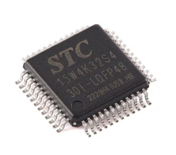
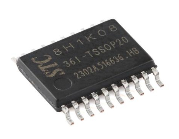
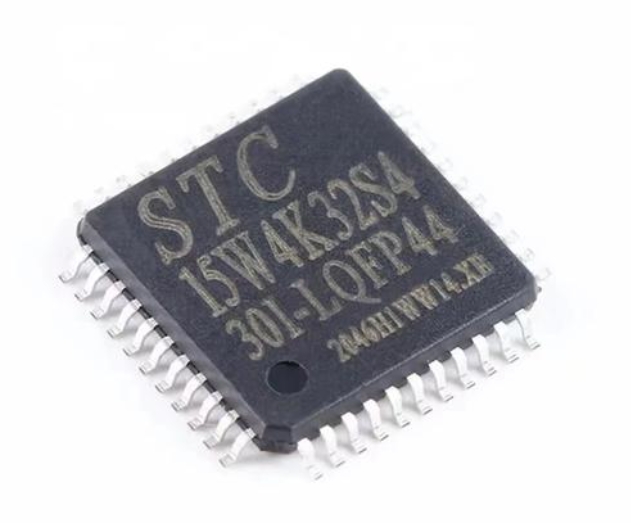
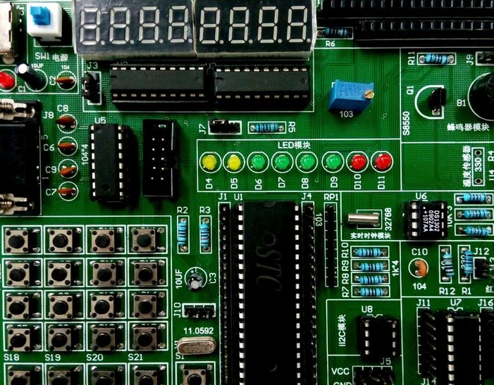
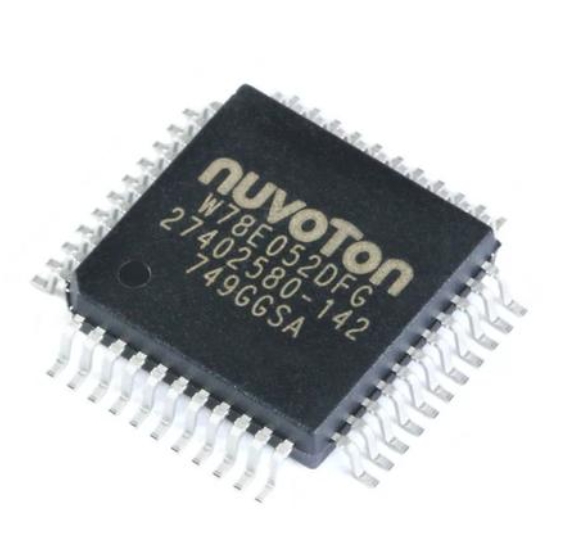
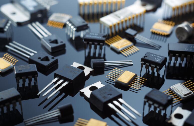
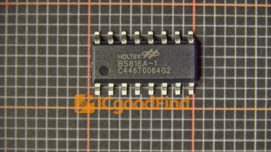
The hardware foundation of an 8051-based traffic light system is crucial for reliable operation. At the heart lies the 8051 microcontroller itself—an 8-bit MCU with a Harvard architecture, featuring 4KB of ROM, 128 bytes of RAM, four 8-bit I/O ports, two 16-bit timers/counters, and a serial communication interface. For a typical traffic light model representing a single intersection, we utilize three signal heads (Red, Yellow, Green) for two perpendicular roads. This requires a minimum of six LEDs, often grouped into two sets controlled via specific output ports of the MCU.
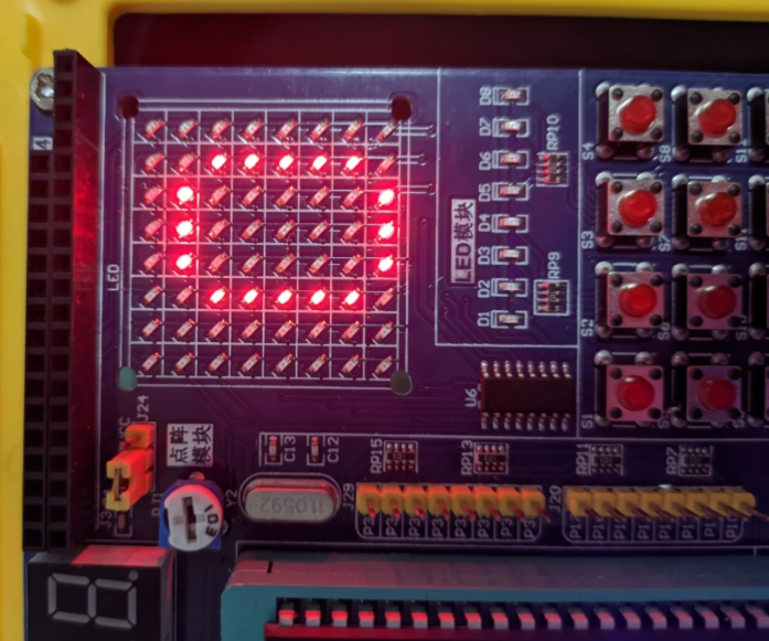
The circuit design involves several key components. The LEDs are connected to the microcontroller’s ports (commonly P1 or P2) through current-limiting resistors (typically 220-330 ohms) to prevent damage from overcurrent. Given the 8051’s limited current sourcing capability, using transistor drivers or ULN2003 Darlington arrays is a recommended practice for brighter LEDs or when simulating higher-power lights. A crystal oscillator circuit (usually 11.0592 MHz or 12 MHz) provides the precise clock pulses necessary for accurate timing delays. A reset circuit, comprising a capacitor and resistor, ensures proper initialization upon power-up. Furthermore, a regulated power supply (5V DC) is essential for the MCU and peripheral components. The elegance of this design lies in its straightforward yet effective interfacing, demonstrating how a minimal set of components can create an autonomous control unit. For sourcing reliable and high-quality components for such educational and prototyping projects, platforms like ICGOODFIND offer a curated selection of microcontrollers, development boards, LEDs, and other electronic parts, ensuring that builders have access to the right tools for successful implementation.
Part 2: Software Logic and Programming Implementation
The intelligence of the traffic light system is embedded in the software running on the 8051 MCU. Programming is typically done in Assembly language or C language, with C being preferred for its structured syntax and easier manageability of complex logic. The core algorithm revolves around managing states and precise timing.
The software defines distinct operational states for the intersection. The primary cycle includes: 1) Green light for Road A while Red for Road B, 2) Transitional Yellow for Road A while Red persists for Road B, 3) Red for both roads for a brief safety interval (all-red), 4) Green for Road B while Red for Road A, and finally, its corresponding yellow and all-red phases. This sequence is managed through a finite state machine implemented in code.
Accurate timing is paramount. The 8051’s built-in Timer/Counter modules are employed to generate precise delays instead of unreliable software loops. Programmers configure the timers by loading values into registers like TH0/TL0 to generate interrupts at specific intervals (e.g., every 50ms). These interrupts service a counter that tracks seconds, triggering state transitions after predefined durations (e.g., 30 seconds for green, 5 for yellow). The software handles port operations by sending appropriate logic levels (1 or 0) to the designated pins to turn LEDs ON or OFF according to the current state. Robust code also includes proper initialization routines for timers, interrupts, and I/O ports (setting ports as output), along with a clear main loop or interrupt service routine that orchestrates the entire sequence seamlessly.
Part 3: System Integration, Enhancements, and Practical Applications
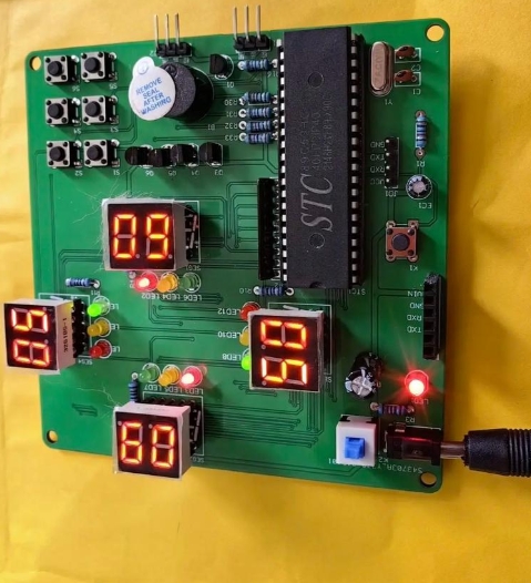
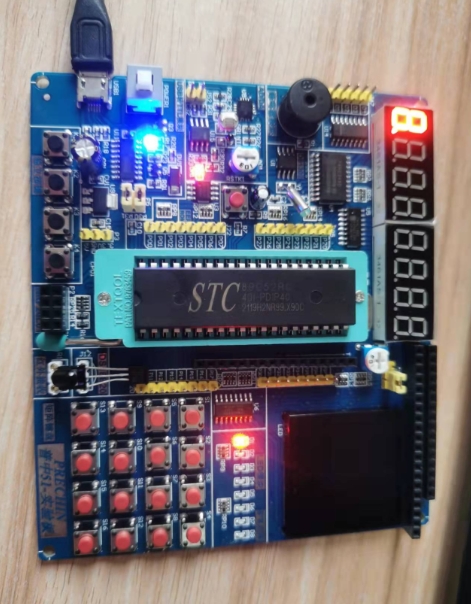
Bringing the hardware and software together involves systematic integration and testing. After assembling the circuit on a breadboard or PCB and writing the program in an IDE like Keil µVision, the code is compiled into hex file format and burned into the microcontroller’s memory using a dedicated programmer. Initial testing focuses on verifying each LED lights up correctly in response to port commands before implementing the full timed sequence.
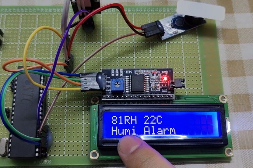
The basic design offers numerous avenues for enhancement, transforming it from a simple model into a more sophisticated system. Key upgrades include: * Pedestrian Crossing Integration: Adding push buttons and walk/don’t walk indicators. * Sensor Integration: Incorporating infrared or vehicle detection sensors to adapt light timings based on real-time traffic density. * Display Countdown Timers: Interfacing seven-segment or LCD displays to show remaining seconds for each signal phase. * Communication Capability: Using the 8051’s serial port to network multiple intersections for coordinated “green wave” sequences. * Emergency Vehicle Override: Implementing an RF or IR receiver module to prioritize signals for emergency services.
These enhancements highlight the project’s relevance beyond academia. The fundamental principles learned here are directly applicable to real-world industrial automation, such as conveyor belt control, batch processing sequences, and automated sorting systems. On a larger scale, they form the basis of modern Intelligent Transportation Systems (ITS), where adaptive traffic control reduces congestion and improves urban mobility.
Conclusion
Designing a traffic light system with the 8051 microcontroller is far more than an academic exercise; it is a holistic journey through embedded system design. It solidifies understanding from schematic design and component selection to algorithmic thinking and low-level programming. This project masterfully illustrates how a modest microcontroller can execute reliable, time-critical control tasks, forming the backbone of countless automated systems in our daily lives. While modern projects may leverage more powerful ARM or AVR chips, the 8051-based design remains an unparalleled educational tool due to its transparent architecture and direct hardware manipulation. For engineers seeking components or inspiration for such foundational projects, resources like ICGOODFIND serve as valuable hubs. Ultimately, mastering this design builds critical competencies that empower developers to tackle increasingly complex challenges in embedded electronics and IoT.