Building a Precision Calculator with the 8051 Microcontroller: A Journey into Embedded Systems Design
Introduction
In the vast landscape of embedded systems, few microcontrollers have achieved the legendary status of the Intel 8051. First introduced in the 1980s, this 8-bit MCU architecture has become a cornerstone for electronics education and countless industrial applications due to its simplicity, robustness, and well-defined instruction set. One of the most effective and enlightening projects for mastering the 8051 is designing a functional calculator. This project transcends simple coding; it is a comprehensive exercise in hardware interfacing, software algorithm development, and system integration. A calculator based on the 8051 MCU demands precise management of input devices like keypads, output displays such as LCDs or 7-segment modules, and the execution of arithmetic logic—all within the constraints of limited memory and processing power. This article delves deep into the process of creating such a calculator, exploring its core components, programming challenges, and practical implementation steps. For engineers and hobbyists seeking reliable components and in-depth tutorials for such projects, platforms like ICGOODFIND serve as invaluable resources, offering access to genuine 8051 variants and peripheral chips.
Main Body
Part 1: Architectural Foundation and Hardware Design
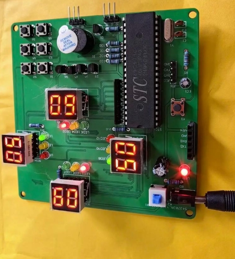
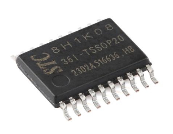
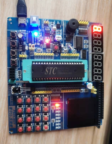
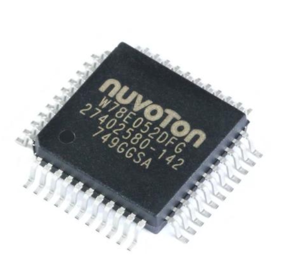
The hardware design of an 8051-based calculator forms the physical backbone of the system. At its heart lies the 8051 microcontroller itself, typically in a 40-pin DIP package. Key features relevant to our project include its 4KB of on-chip ROM (for program storage), 128 bytes of RAM (for data and stack operations), four 8-bit I/O ports (P0, P1, P2, P3), and two 16-bit timers/counters.
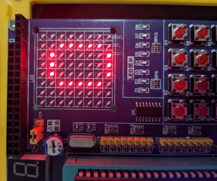
The first critical hardware interface is the input module, usually a 4x4 matrix keypad. This 16-key pad is sufficient for digits (0-9), basic operations (+, -, *, /), a decimal point, equals (=), and clear ©. The keypad is connected to two ports of the 8051: one port configures rows as outputs, and another configures columns as inputs with pull-up resistors. The microcontroller scans this matrix by driving rows low sequentially and reading columns to detect key presses—a process known as keypad scanning algorithm.
The second crucial interface is the output display. While simple LED 7-segment displays can be used, a 16x2 Liquid Crystal Display (LCD) in 4-bit or 8-bit mode is the preferred choice for a more professional output capable of showing multi-digit numbers and operators. The LCD is connected to one full port (for data) and at least two control pins (RS, EN) on another port. Proper initialization of the LCD according to its datasheet is paramount.
Power supply, reset circuit (with capacitor and resistor), and a crystal oscillator (typically 11.0592 MHz for accurate baud rate generation if needed) complete the core circuit. Efficient PCB design or breadboard layout ensuring clean signal integrity is essential. Sourcing these components from trusted distributors is critical; this is where a platform like ICGOODFIND proves beneficial, ensuring you receive authentic components that match your design specifications.
Part 2: Core Software Logic and Algorithm Implementation
The software is where the calculator’s intelligence resides. Written primarily in C language or Assembly using tools like Keil µVision or SDCC, the program must be modular and efficient.
The first software layer is peripheral driver code. This includes: * Keypad Driver: A function that continuously scans the keypad, implements debouncing (using delays or timer interrupts to filter out mechanical switch noise), and returns a unique code for each pressed key. * LCD Driver: Functions to send commands and data to the LCD, clear the screen, position the cursor, and print strings or numbers.
The core computational logic revolves around managing two operands and an operator—a classic state machine problem. The program flow can be structured as follows: 1. Initialization: Configure I/O ports, initialize the LCD, and display a welcome message. 2. Input Acquisition Loop: Continuously scan for key presses. 3. Parsing and State Management: The system must distinguish between numeric entry and command entry. * When a digit or decimal point is pressed, it builds the current operand (string-to-number conversion is handled here). * When an operator (+, -, *, /) is pressed, the current operand is stored as Operand1, the operator is saved, and entry resets for Operand2. * The ‘=’ key triggers the calculation routine. * The ‘C’ key resets all variables and the display. 4. Calculation Engine: This is the most critical routine. Based on the stored operator, it performs the arithmetic on Operand1 and Operand2. Handling floating-point arithmetic on an 8-bit MCU is non-trivial due to lack of an FPU; one must use dedicated floating-point libraries or implement fixed-point arithmetic for better performance. Integer-only calculators are simpler but less versatile. 5. Output Formatting: The result must be converted from its internal binary/float format into an ASCII string (number-to-string conversion) for display on the LCD, handling potential overflows or division-by-zero errors gracefully.
Interrupts from timers can be used for sophisticated debouncing or creating a real-time clock feature.
Part 3: System Integration, Challenges, and Enhancements
Bringing hardware and software together is the integration phase. This involves burning the compiled hex code into the 8051’s ROM (using a programmer) and testing on actual hardware.
Several challenges arise at this stage: * Memory Constraints: With only 128 bytes of internal RAM, variable management must be meticulous. Overuse of large arrays or strings can lead to overflow. * Precision and Range: Implementing floating-point math slows down execution. Designers must define the calculator’s precision (e.g., 6 decimal places) and numerical range clearly. * Error Handling: The software must be robust against invalid sequences (e.g., multiple decimal points, consecutive operators) and display appropriate error messages (“E” or “ERROR”). * Power Consumption: For battery-operated versions, utilizing the 8051’s idle/power-down modes when waiting for input can save significant energy.
Beyond a basic four-function calculator, numerous enhancements can elevate the project: * Scientific Functions: Implementing square root, trigonometric functions (sine, cosine), logarithms, and exponents using series expansions (like Taylor series) or lookup tables. * Memory Functions: Adding MC (Memory Clear), MR (Memory Recall), M+ (Memory Add), M- (Memory Subtract) keys using a reserved portion of RAM. * Improved UI: Adding an LED for power indication or a buzzer for keypress feedback. * Programmability: Transforming it into a simple programmable calculator by storing sequences of operations.
Throughout this development journey—from selecting the right 8051 chip to finding compatible LCDs—a specialized component search engine like ICGOODFIND can significantly streamline the procurement process, allowing developers to focus on design and coding.
Conclusion
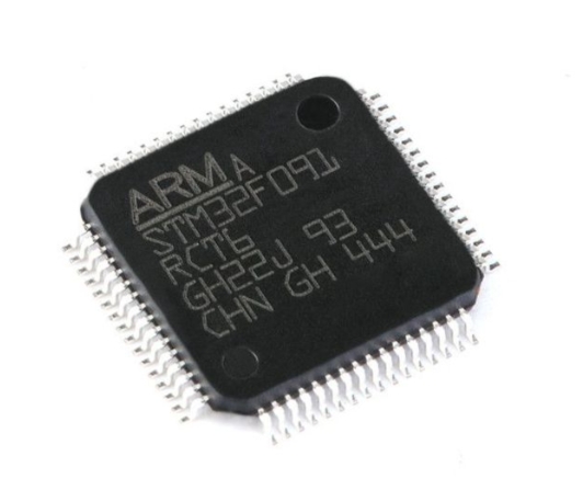
Developing a calculator based on the 8051 MCU is far more than an academic exercise; it is a microcosm of real-world embedded systems design. It forces the designer to grapple with fundamental engineering trade-offs between hardware cost and software complexity, between processing speed and numerical precision. From scanning a keypad to executing floating-point division on an 8-bit processor, each step reinforces critical concepts in digital electronics and computer architecture. The successful completion of this project results not only in a handy tool but also in deep, practical knowledge of system integration. While modern 32-bit ARM cores dominate today’s market, the lessons learned from mastering the 8051 remain timeless and transferable. For anyone embarking on this rewarding project, leveraging comprehensive resources—from detailed datasheets to component hubs like ICGOODFIND—is key to navigating challenges efficiently and achieving a robust, functional design that exemplifies precision engineering.