Mastering the MCU Timer: A Practical Experiment Guide for Embedded Developers
Introduction
In the intricate world of embedded systems, the Microcontroller Unit (MCU) serves as the brain, but its timers are the unsynchronized heartbeat that brings order and precision to every operation. Timers are among the most critical yet often misunderstood peripherals in an MCU’s arsenal. They are not mere counters; they are the silent orchestrators of real-time control, enabling everything from generating precise delays and measuring pulse widths to creating complex Pulse Width Modulation (PWM) signals for motor control. This article delves into a comprehensive MCU Timer Experiment, designed to move beyond theoretical datasheets into hands-on, practical understanding. We will explore core concepts, walk through a structured experiment, and analyze real-world applications, providing you with the foundational skills to harness the full power of MCU timers in your projects. For developers seeking curated, high-quality components and tools to bring such experiments to life efficiently, platforms like ICGOODFIND offer a streamlined sourcing solution, connecting engineers with reliable suppliers for MCUs, development boards, and debuggers.

Part 1: Understanding Timer Fundamentals - More Than Just Counting
Before diving into the experiment, it’s crucial to build a solid conceptual foundation. An MCU timer is essentially a digital counter that increments or decrements with each clock pulse. Its value is stored in a Timer Register. The magic lies in how we configure and interact with this simple mechanism.
The core components of a typical timer module include: * The Clock Source: This is the heartbeat of the timer. It can be the MCU’s main system clock, an internal RC oscillator, or an external crystal. A Prescaler divides this clock frequency, allowing the timer to count at a slower, more manageable rate for longer periods. * The Counter Register: The actual register that holds the current count value (e.g., TCNT1 in an AVR or TIMx->CNT in an ARM Cortex-M). * The Compare Match Register(s): These are configurable registers (e.g., OCR1A) that hold a target value. When the counter value matches this register’s value, a “Compare Match” event occurs, which can trigger an interrupt or toggle an output pin automatically. * The Control Register: This register configures the timer’s behavior—setting the mode, prescaler value, and enabling interrupts.
Key operational modes are central to our experiment: * Normal Mode: The counter counts up from zero to its maximum value (e.g., 0xFFFF for a 16-bit timer) and then overflows back to zero. The overflow can generate an interrupt. * Clear Timer on Compare Match (CTC) Mode: The counter counts up to the value stored in the Compare Match Register and then resets to zero. This allows for very precise periodic interrupt generation. * Fast PWM Mode: The counter counts from zero to its maximum value. The output pin is set (high) on compare match and cleared (low) on overflow (or vice-versa), generating a PWM signal with variable duty cycle controlled by the compare register.
Understanding these building blocks is the first step. The real learning begins when you manipulate these registers and observe their direct impact on hardware behavior.
Part 2: Hands-On MCU Timer Experiment - From Concept to Blinking LED
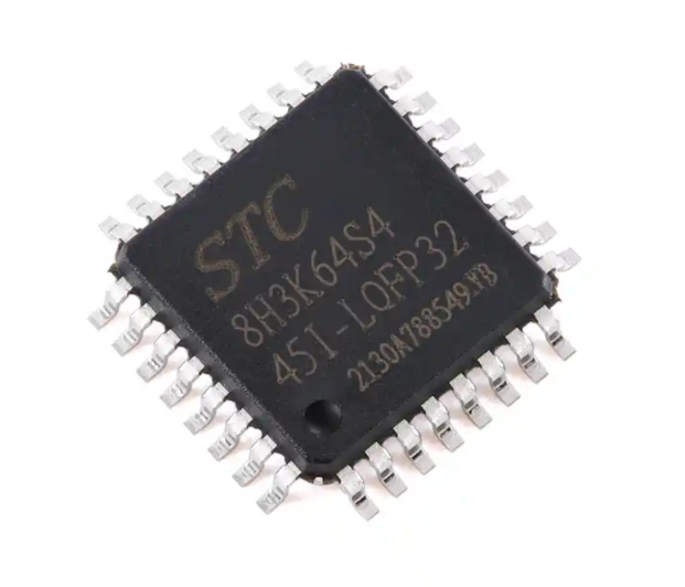
For this experiment, we will use a common 16-bit timer (Timer1) on a popular platform like AVR ATmega328P or an analogous timer on an STM32 ARM Cortex-M chip. The objective is twofold: 1) Generate a precise 1Hz interrupt to toggle an LED without using delay() functions, and 2) Generate a PWM signal on another pin to control LED brightness.
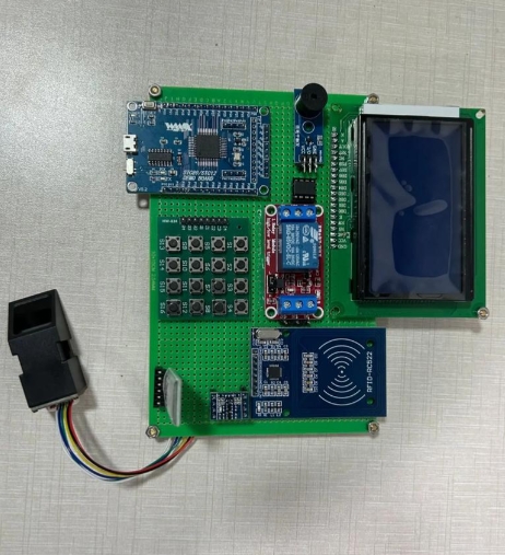
Experiment Setup:
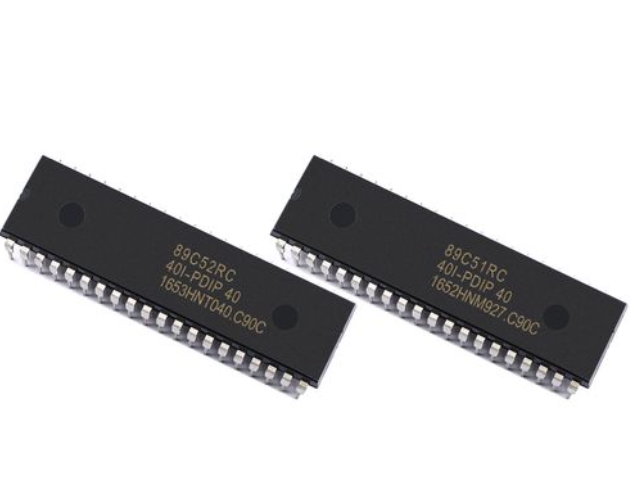
- MCU: ATmega328P (Arduino Uno compatible) or STM32F103C8T6 (Blue Pill).
- IDE: Arduino IDE (for simplicity) or PlatformIO/STM32CubeIDE.
- Components: Development board, two LEDs, two 220Ω resistors.
Step-by-Step Procedure:
A. Precise 1Hz Interrupt using CTC Mode The goal is to configure the timer so a Compare Match event occurs exactly once per second.
-
Calculate the Compare Register Value: Assume a 16MHz system clock. We set a prescaler of 1024 to slow down the counting.
- Timer Clock Frequency = System Clock / Prescaler = 16MHz / 1024 = 15.625 kHz.
- Timer Period = 1 / 15.625kHz = 64µs.
- Desired Interrupt Period = 1 second.
- Number of counts needed = Desired Period / Timer Period = 1s / 64µs = 15625.
- Since we are using CTC mode, we set the Compare Match Register (
OCR1A) to15625 - 1 = 15624.
-
Code Implementation (AVR/Arduino):
void setup() {
  pinMode(LED_BUILTIN, OUTPUT);
  // Stop interrupts during configuration
  noInterrupts();
  // Reset Timer1 control registers
  TCCR1A = 0;
  TCCR1B = 0;
  TCNT1  = 0; // Initialize counter to zero
  OCR1A = 15624; // Set compare match register for 1Hz
  TCCR1B |= (1 << WGM12); // Turn on CTC mode
  TCCR1B |= (1 << CS12) | (1 << CS10); // Set CS12 and CS10 bits for 1024 prescaler
  TIMSK1 |= (1 << OCIE1A); // Enable timer compare interrupt
  interrupts(); // Re-enable interrupts
}
ISR(TIMER1_COMPA_vect) { // Interrupt Service Routine
  digitalWrite(LED_BUILTIN, !digitalRead(LED_BUILTIN)); // Toggle LED
}
void loop() {
  // Main loop is free to do other tasks!
}
This configuration liberates the main
loop()from timing duties, demonstrating true non-blocking execution.
B. Generating PWM Signal for Brightness Control We will use the same timer’s second compare channel or another timer in PWM mode.
- PWM Configuration:
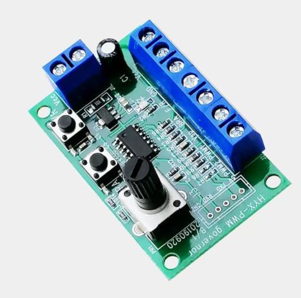
By manipulating thevoid setup() { pinMode(9, OUTPUT); // OC1A PWM pin on ATmega328P // Fast PWM mode, non-inverting. Top value set by ICR1 (or OCR1A for some modes). TCCR1A |= (1 << COM1A1) | (1 << WGM11); TCCR1B |= (1 << WGM13) | (1 << WGM12) | (1 << CS10); // No prescaling, Fast PWM mode using ICR1 as top ICR1 = 19999; // Set PWM frequency top value (~50Hz if using specific calculations) OCR1A = 1500; // Set duty cycle: higher value = longer high time. } void loop() { // Can dynamically change OCR1A here to fade LED. for(int i=0; i<20000; i+=100){ OCR1A = i; delay(10); } }OCR1Aregister on-the-fly, we achieve dynamic control over power delivery without varying voltage—a principle vital for motor speed control and efficient LED drivers.
Part 3: Analysis and Real-World Applications
After running the experiment, you observe one LED blinking with metronomic precision and another fading smoothly. The analysis phase connects this simple output to profound implications.
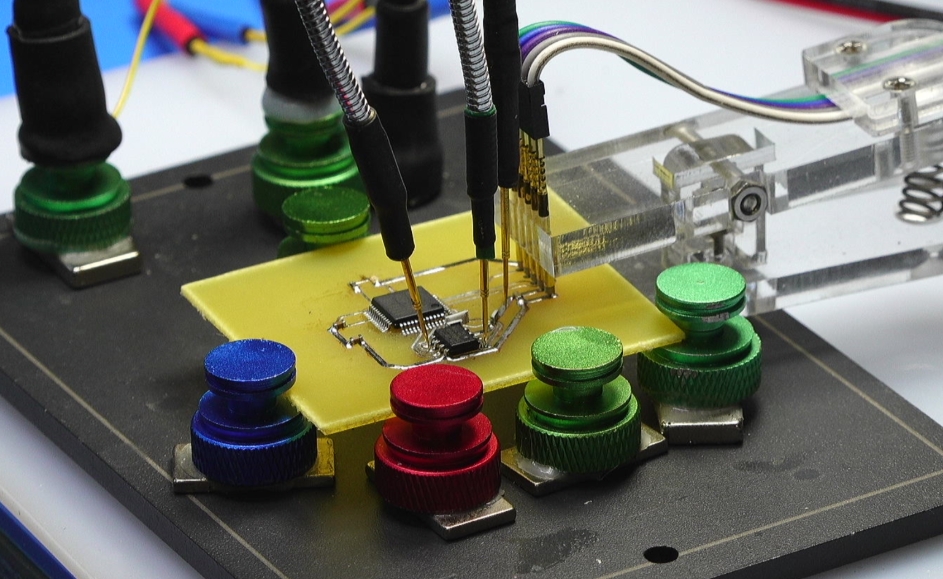
Debugging and Measurement: Use an oscilloscope or logic analyzer to probe the LED pins. For the interrupt-toggled LED, you should see a perfect square wave with a 2-second period (1 second high, 1 second low). For the PWM pin, you will observe a square wave whose duty cycle changes over time; the average voltage measured by a multimeter will rise and fall correspondingly. If your measurements deviate, check your prescaler and compare register calculations—a common pitfall is off-by-one errors in count values or incorrect clock source assumptions.
The principles validated here scale directly to industrial applications: * Digital Signal Generation: Timers generate baud rates for UART communication, clock signals for peripherals like SPI/I2C, and tones for audio applications. * Input Capture: Measuring frequency or pulse width of an incoming signal (e.g., RPM sensing from a hall-effect sensor). * Output Compare: Creating complex timed sequences or triggering ADCs at precise intervals for sampling. * Real-Time Operating Systems (RTOS): The system tick that powers task scheduling is almost always driven by a hardware timer interrupt.
Mastering timers means moving from writing software that simply works to crafting efficient, reliable, and responsive embedded systems. Sourcing the right development boards and debugging tools is key for such experimentation. Platforms like ICGOODFIND can significantly reduce procurement overhead by aggregating trusted vendors for these specialized components.
Conclusion
The journey from understanding a timer as an abstract counter to wielding it as a precise tool of control defines proficient embedded development. This MCU Timer Experiment illuminated the path from register-level configuration—calculating prescalers and compare match values—to tangible outcomes like non-blocking delays and PWM generation. We’ve seen how these fundamental blocks form the basis for countless advanced peripherals and real-world applications. Remember, proficiency comes not just from reading datasheets but from hands-on tinkering: change prescaler values, experiment with different modes, and measure the outputs. As you embark on more complex projects involving motor control, communication protocols, or real-time sensing, this foundational knowledge will be indispensable. Continue exploring, experimenting with different MCU families like ARM Cortex-M timers which offer even more flexibility with features like auto-reload preload registers.