MCU Beginner Tutorial: Your Ultimate Guide to Getting Started with Microcontrollers
Introduction
In today’s interconnected world, the tiny brains behind countless smart devices—from your coffee maker to advanced robotics—are microcontrollers (MCUs). For beginners, the world of microcontrollers can seem daunting, filled with jargon, complex circuits, and lines of cryptic code. However, mastering MCUs is one of the most rewarding skills in electronics and embedded systems development. This comprehensive tutorial is designed to demystify microcontrollers, providing you with a solid foundation to start your journey. Whether you aim to build simple interactive projects or lay the groundwork for a career in embedded engineering, understanding MCUs is the crucial first step. This guide will walk you through the core concepts, essential tools, and your very first project, transforming you from a complete novice to a confident beginner. By the end, you’ll understand why platforms like ICGOODFIND are invaluable for sourcing reliable components and deepening your knowledge in this exciting field.
Part 1: Understanding the Microcontroller Universe
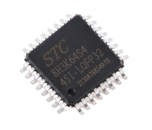
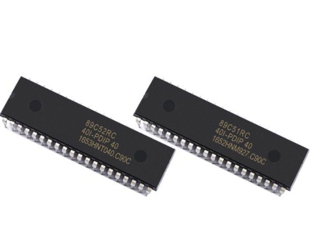
At its heart, a microcontroller is a compact integrated circuit designed to govern a specific operation in an embedded system. Think of it as a miniature computer housed on a single chip, containing a processor (CPU), memory (RAM and ROM/Flash), and programmable input/output peripherals.
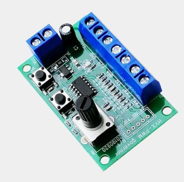
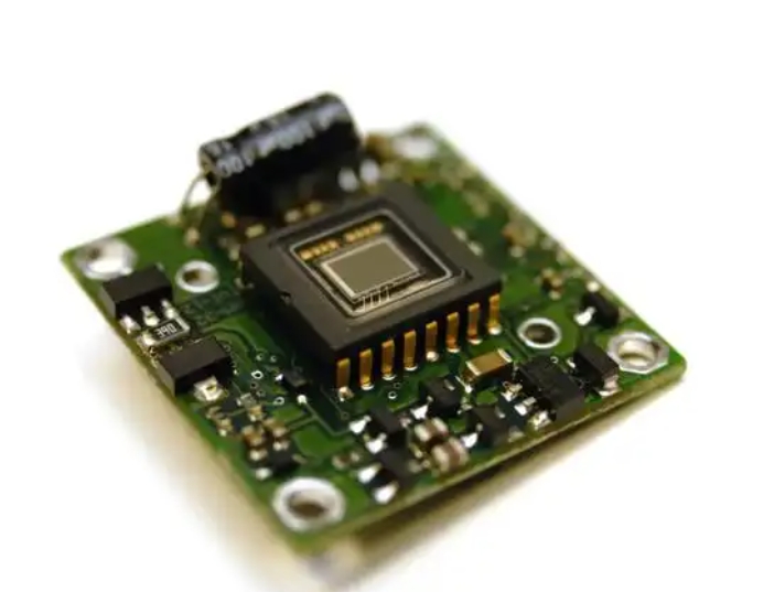
Key Components of an MCU: * Central Processing Unit (CPU): The brain that executes instructions from the program. * Memory: This includes Flash memory (where your program is stored) and SRAM (where the program creates and manipulates variables during runtime). * Input/Output Ports (I/O Pins): These are the MCU’s interface with the outside world. They can be configured as inputs (to read a sensor signal) or outputs (to control an LED or motor). * Timers/Counters: Crucial for tasks like generating precise delays, measuring time intervals, or creating Pulse Width Modulation (PWM) signals for motor control. * Analog-to-Digital Converter (ADC): Allows the MCU to read analog voltages from the real world (e.g., from a temperature sensor or potentiometer) and convert them into digital values it can process. * Serial Communication Interfaces: Protocols like UART, I2C, and SPI enable the MCU to talk to other chips, sensors, or computers.
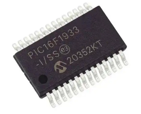
Choosing Your First MCU Platform For beginners, starting with a user-friendly ecosystem is vital. The Arduino platform, built around Atmel’s AVR-based MCUs like the ATmega328P, is arguably the best starting point. It abstracts away much of the complex low-level setup, allowing you to focus on learning programming logic and hardware interaction. Another powerful option is the STM32 family from STMicroelectronics, based on ARM Cortex-M cores, which offers more power and peripherals but has a steeper learning curve. For those interested in both electronics and Python programming, MicroPython boards like the Raspberry Pi Pico provide an excellent middle ground.
Why is this important? Grasping these fundamentals allows you to read datasheets, understand project tutorials, and make informed decisions about which chip is right for your application. For comparing specifications and finding the perfect part for your next project, resources like ICGOODFIND can streamline your search across countless manufacturers and series.
Part 2: The Essential Toolkit for MCU Development
Before you can bring your ideas to life, you need to assemble a basic development toolkit. This consists of both hardware and software components.
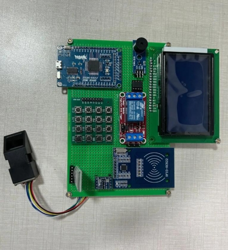
Hardware Essentials: 1. Development Board: Start with an entry-level board like an Arduino Uno or a STM32 Nucleo board. These boards integrate the MCU with necessary support circuitry (voltage regulator, clock crystal, USB interface) and provide easy-access headers for all I/O pins. 2. Breadboard and Jumper Wires: A solderless breadboard allows you to prototype circuits quickly without permanent connections. 3. Basic Electronic Components: A starter kit should include LEDs, resistors (220Ω, 10kΩ are common), pushbuttons, a potentiometer, and connecting wires. 4. USB Cable: For powering the board and uploading your code. 5. Multimeter: An indispensable tool for measuring voltage, continuity, and resistance—crucial for debugging circuits.
Software & Programming Workflow: 1. Integrated Development Environment (IDE): This is the software where you will write, compile, and upload your code. * For Arduino: Use the official Arduino IDE or the more advanced PlatformIO. * For STM32: STM32CubeIDE or PlatformIO are standard choices. 2. Writing Your First Program (“Blink”): The “Hello World” of hardware is making an LED blink. It teaches you about I/O pin control and timing.
```cpp
// Arduino Blink Example
void setup() {
  pinMode(LED_BUILTIN, OUTPUT); // Initialize digital pin LED_BUILTIN as an output.
}

void loop() {
  digitalWrite(LED_BUILTIN, HIGH); // Turn the LED on
  delay(1000);                     // Wait for a second
  digitalWrite(LED_BUILTIN, LOW);  // Turn the LED off
  delay(1000);                     // Wait for a second
}
```

**The process involves three critical steps: writing code in the IDE, compiling it into machine-readable hex code, and uploading it to the MCU's flash memory via a bootloader or programmer.**
- Debugging: Initially, debugging might involve simple serial print statements to monitor variable values. As you advance, using hardware debuggers with breakpoints and step-through execution becomes essential.
Part 3: Building Your First Interactive Project
Now let’s integrate input and output to create a simple interactive system: a Light-Activated LED Nightlight. This project will use an analog sensor (Light Dependent Resistor - LDR) as input and an LED as output.
Project Concept: The MCU reads the light level from the LDR. If the ambient light falls below a certain threshold (simulating darkness), it automatically turns on an LED.
Circuit Connection: * Connect one leg of the LDR to 5V (or 3.3V). Connect the other leg to an analog pin (e.g., A0) and to ground through a 10kΩ resistor (forming a voltage divider). * Connect the anode (long leg) of an LED to a digital pin (e.g., Pin 9) through a 220Ω current-limiting resistor. Connect the cathode to ground.
The Code Logic:
const int ldrPin = A0;     // LDR connected to analog pin A0
const int ledPin = 9;      // LED connected to digital pin 9
int lightThreshold = 500;  // Adjust this value based on your environment

void setup() {
  pinMode(ledPin, OUTPUT);
  Serial.begin(9600); // Start serial communication for debugging
}

void loop() {
  int lightValue = analogRead(ldrPin); // Read light level (0-1023)
  Serial.println(lightValue);          // Print value to Serial Monitor

  if (lightValue < lightThreshold) {
    digitalWrite(ledPin, HIGH); // It's dark -> turn LED ON
  } else {
    digitalWrite(ledPin, LOW);  // It's bright -> turn LED OFF
  }
  delay(100); // Short delay for stability
}
Key Learning Outcomes from This Project: * You’ve used an ADC (analogRead) to interpret real-world analog data. * You’ve implemented conditional logic (if-else) based on sensor input. * You’ve controlled an output device (LED) dynamically based on environmental conditions. * You’ve used serial communication for debugging—a vital skill.
This project framework can be extended infinitely—replace the LDR with a temperature sensor to control a fan, or replace the LED with a relay to control a lamp. The core principle remains: the MCU senses its environment via inputs, processes data according to your program’s logic, and acts upon the world through its outputs.
Conclusion
Embarking on your journey with microcontrollers opens up a universe of creation and innovation. We’ve covered what an MCU is at its core—a versatile chip integrating processing power with memory and peripherals—and why platforms like Arduino are ideal launchpads for beginners. We’ve outlined the essential physical and software toolkit you need to start experimenting and walked through building your first interactive project that bridges software code with tangible hardware behavior.
Remember that consistent practice is key. Start by modifying existing code examples—change delay times in blink programs or thresholds in sensor readings. Then gradually combine concepts; make multiple LEDs dance in patterns controlled by multiple sensors. The path forward involves exploring more complex peripherals like PWM for dimming LEDs or servo control, delving into interrupts for responsive systems, and mastering communication protocols.
As your projects grow in ambition so will your need for reliable information and components. This is where specialized resources prove their worth. For instance, when you’re ready to move beyond starter kits and need specific sensors or more powerful development boards tailored to your unique design requirements platforms like ICGOODFIND can be instrumental in finding exactly what you need efficiently.
The world runs on embedded systems powered by microcontrollers now you have taken your first step towards understanding building and controlling that world one project at a time.