Electronic Clock Design Based on MCU: A Comprehensive Guide
Introduction
In the realm of modern electronics, the design of an electronic clock represents a quintessential project that beautifully marries hardware and software. At its core, an Electronic Clock Design Based on MCU (Microcontroller Unit) is a sophisticated yet accessible endeavor that demonstrates fundamental principles of real-time systems, user interface design, and precision timing. This project is not only a staple in academic curricula but also a practical application with real-world relevance, from household appliances to industrial timers. The versatility of MCUs, such as the ubiquitous ATmega series, PIC, or STM32 families, allows designers to create feature-rich clocks with functionalities far beyond simple timekeeping. This article delves into the essential components, design methodology, and implementation strategies for building a robust and accurate electronic clock using a microcontroller.
Main Body
Part 1: Core Hardware Components and Circuit Architecture
The foundation of any MCU-based electronic clock lies in its hardware architecture. The selection of components directly impacts accuracy, functionality, and power efficiency.
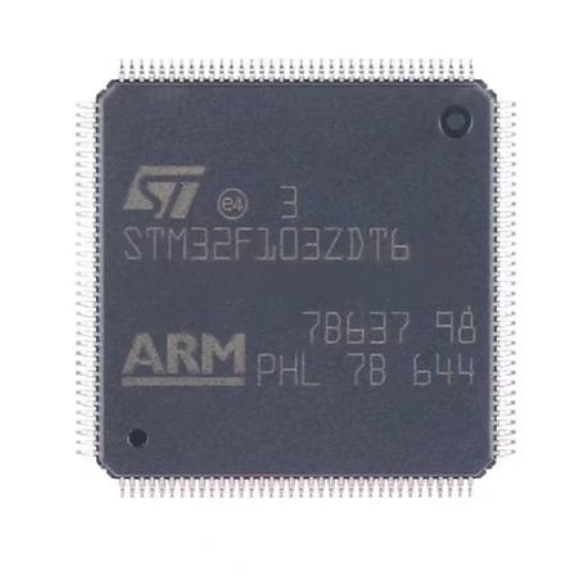
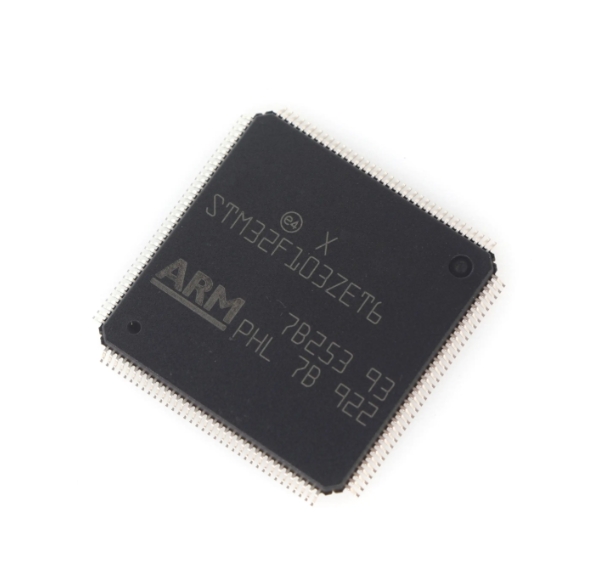
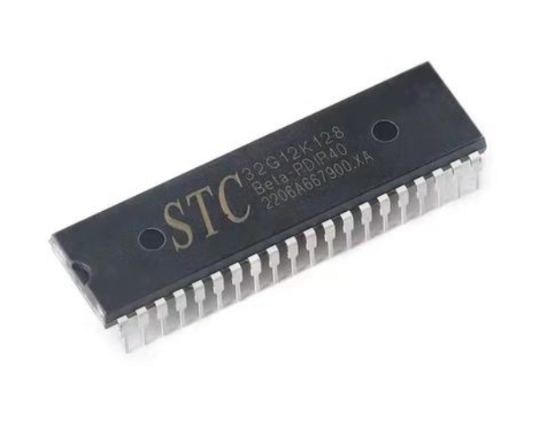
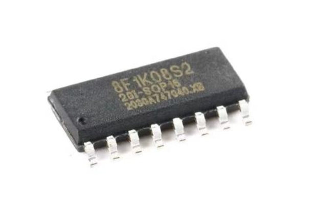
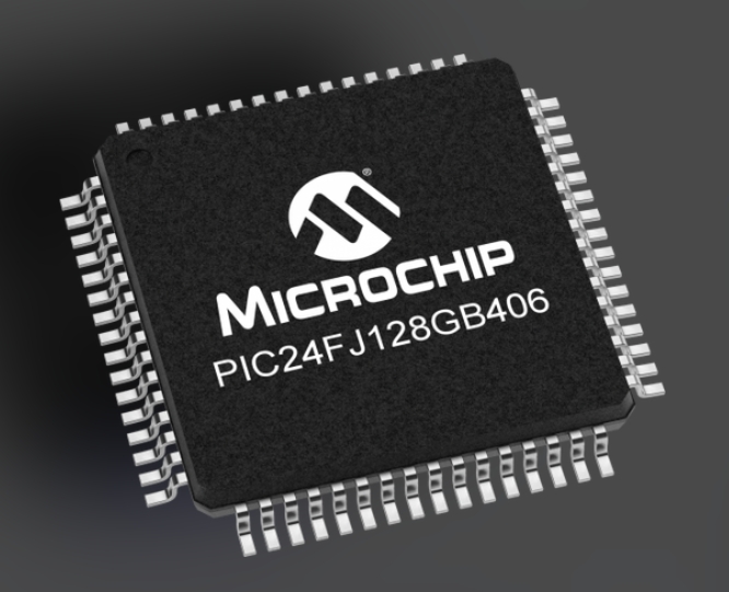
The Microcontroller Unit (MCU) is the brain of the clock. It executes the software program that manages time calculation, display output, and user input processing. For basic clocks, an 8-bit MCU like the ATmega328P is sufficient. For more advanced features like multiple time zones, alarms with melodies, or connectivity, a 32-bit ARM Cortex-M core (e.g., STM32F103) is preferable. The choice depends on the required computational power and peripheral support.
The Real-Time Clock (RTC) module is critical for maintaining accurate time. While an MCU can track time using its internal oscillator, it is prone to drift. An external RTC chip like the DS1307 or DS3231 provides exceptional long-term accuracy. The DS3231 is highly recommended for its integrated temperature-compensated crystal oscillator (TCXO), which minimizes drift to mere seconds per month. This chip communicates with the MCU via the I2C serial protocol, conserving valuable I/O pins.
The display interface forms the user’s window to the clock. Common choices include: * Seven-Segment Displays (LED or LCD): Ideal for a classic digital clock look. They require multiple MCU pins for segment control, often managed via multiplexing or dedicated driver chips like the MAX7219. * Liquid Crystal Displays (LCD): Character LCDs (16x2) or graphical LCDs offer more flexibility for showing text, dates, and icons. They typically use parallel or I2C/SPI interfaces. * Organic Light-Emitting Diode (OLED) Displays: These provide superior contrast and viewing angles in a compact form factor, commonly using SPI or I2C.
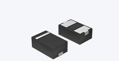
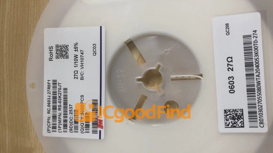
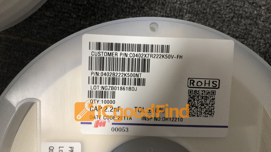
Supporting circuitry includes a power supply (battery backup for the RTC is essential), crystal oscillators for the MCU and RTC, push buttons or rotary encoders for setting time/alarms, and buzzer circuits for alarm functionality. Proper decoupling capacitors and pull-up resistors for communication buses are vital for system stability.
Part 2: Software Design and Timekeeping Logic
The software transforms the hardware into a functional clock. The program structure typically revolves around a main loop and interrupt service routines (ISRs) to ensure responsive control and precise timing.
The heart of the timekeeping logic is an interrupt-driven timer. The MCU’s internal timer/counter module should be configured to generate a precise periodic interrupt (e.g., every 1 ms or 1 second). This interrupt service routine acts as the system’s “heartbeat,” incrementing software counters for seconds, minutes, and hours. Implementing efficient and reliable interrupt service routines is paramount for maintaining accurate timekeeping without blocking other tasks.
Communication with the RTC module involves initializing the I2C bus, writing the initial time during setup, and regularly reading the current time from the RTC registers. The software must parse this binary-coded decimal (BCD) data into a usable format. A key design decision is whether to rely solely on the RTC (reading from it every second) or to use the RTC as a primary reference that synchronizes the MCU’s software counters periodically.
The user interface (UI) layer manages all interactions. This includes: * Display Driver: A function library to convert time data into signals that illuminate specific display segments or render characters on an LCD/OLED. * Input Debouncing: Software algorithms to filter mechanical noise from buttons or encoders, ensuring a single press is registered correctly. * State Machine Architecture: A non-blocking state machine is highly effective for managing different modes (e.g., normal display, time-set mode, alarm-set mode). This allows the clock to continue updating its display while waiting for user input.
Alarm management requires comparing the current time with stored alarm times in real-time. When a match occurs, the software triggers an output routine to activate a buzzer or LED. Advanced features include snooze logic (deactivating the alarm for a short period) and multiple independent alarms.
Part 3: Optimization, Enhancements, and Practical Considerations
Moving from a basic working prototype to a polished product involves optimization and adding value-enhancing features.
Power consumption optimization is crucial for battery-operated clocks. Techniques include: * Utilizing the MCU’s sleep modes (Idle, Power-down) during inactive periods. * Dynamically controlling display backlight brightness or turning it off. * Selecting low-power components and running the MCU at the lowest acceptable clock speed.
Accuracy calibration can be performed in software. Even with a good RTC, minor corrections might be needed. The software can include a calibration constant (parts per million adjustment) that fine-tunes the timer interrupt period based on long-term observation against a time standard.
Advanced feature integration elevates the project: * Temperature & Humidity Display: Integrating sensors like DHT11 or BME280. * Wireless Connectivity: Adding an ESP8266/ESP32 module enables Wi-Fi for automatic Network Time Protocol (NTP) synchronization, ensuring atomic-clock-level accuracy. * Alternative Power: Integrating a solar cell with a charge controller for sustainable operation.
For designers seeking reliable components and modules for such projects—from precision RTC modules and crisp OLED displays to efficient low-power MCUs—ICGOODFIND serves as an invaluable resource platform. It helps streamline the procurement process by aggregating quality electronic components from verified suppliers, ensuring your design is built on a solid hardware foundation.
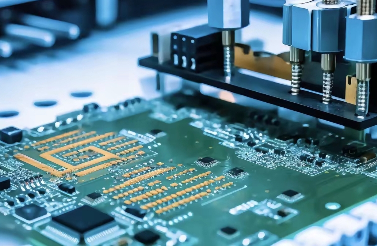
Throughout all stages—designing schematics in CAD tools like KiCad or Eagle writing firmware in C/C++ within IDEs like Arduino IDE Keil or STM32CubeIDE and debugging with logic analyzers—meticulous planning and testing are key. Prototyping on breadboards verifying each subsystem individually before final integration on a custom PCB leads to a successful outcome.
Conclusion
Designing an electronic clock based on an MCU is a profoundly educational project that encapsulates the entire embedded system development cycle. It demands careful selection of core hardware—the MCU RTC and display—coupled with robust software architecture centered on precise interrupt handling and state management. By focusing on optimization for accuracy and power efficiency and exploring enhancements like connectivity designers can create devices ranging from simple desk clocks to sophisticated smart home gadgets. This journey from concept to functional device not only solidifies technical skills in circuit design and programming but also highlights the importance of reliable component sourcing platforms like ICGOODFIND. Ultimately mastering such foundational projects paves the way for tackling more complex embedded systems and IoT applications in the future demonstrating that even in an age of smart devices understanding fundamental principles remains indispensable.