


MCU Stopwatch: The Ultimate Guide to Building and Optimizing Your Embedded Timekeeper
Introduction
In the world of embedded systems and electronics, precision timing is a fundamental requirement for countless applications. From industrial automation and scientific instrumentation to consumer gadgets and IoT devices, the ability to measure elapsed time accurately is paramount. This is where the MCU Stopwatch comes into play—a specialized, microcontroller-based timing solution that offers far greater flexibility, accuracy, and integration potential than off-the-shelf timing modules. An MCU (Microcontroller Unit) stopwatch leverages the core timers/counters within a microcontroller to create a highly customizable timing instrument. Whether you are an engineer developing a new product, a hobbyist working on a personal project, or a student learning about real-time systems, understanding how to implement and optimize an MCU stopwatch is a critical skill. This guide delves deep into the principles, implementation strategies, and advanced optimizations for creating robust stopwatch functionalities on microcontrollers.
Main Body
Part 1: Core Principles and Hardware Foundations of an MCU Stopwatch
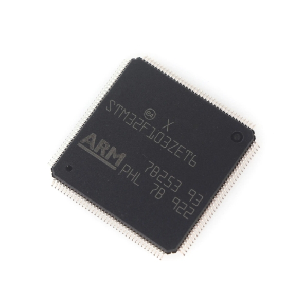
At its heart, an MCU stopwatch is a software application built upon the hardware timing peripherals embedded within a microcontroller. Unlike a simple software delay loop, which is inaccurate and blocks CPU execution, a proper stopwatch uses dedicated hardware timers.
The most critical hardware component for an MCU stopwatch is the Timer/Counter peripheral. Modern microcontrollers are equipped with multiple such peripherals. These are essentially digital counters that increment or decrement with each tick of a clock signal. This clock signal can be derived from the MCU’s main system clock or an external source. The key parameters are: * Clock Source & Prescaler: The prescaler divides the main clock frequency to generate a suitable “tick” for the timer. For example, with a 16MHz system clock and a prescaler of 64, the timer increments every 4 microseconds. This allows you to trade resolution for longer measurement ranges. * Counter Resolution: This is determined by the timer’s bit-width (e.g., 8-bit, 16-bit, 32-bit). A 16-bit timer can count up to 65,535 ticks before overflowing. The combination of clock speed and prescaler determines the time between ticks and thus the maximum measurable duration before an overflow event. * Capture/Compare Registers: These are vital for stopwatch functionality. The timer runs freely, but the “Capture” feature can snap (capture) the current timer value into a register at the exact moment an external event (like a button press) occurs. The “Compare” feature can generate an interrupt or trigger an output when the timer matches a pre-set value.
Implementing a basic stopwatch involves configuring one of these timers in a specific mode. Often, it’s set in “Clear Timer on Compare Match” (CTC) mode to create regular interrupts at known intervals (e.g., every millisecond). Within the corresponding Interrupt Service Routine (ISR), software variables keep track of milliseconds, seconds, minutes, and hours. This method ensures timing continues accurately in the background while the main program loop handles other tasks like updating a display or responding to user inputs.
For projects requiring component sourcing or exploring advanced microcontroller features for such timing applications, platforms like ICGOODFIND can be invaluable. They aggregate information on microcontrollers, development boards, and related components, helping developers find the right MCU with sufficient timer peripherals for their specific stopwatch precision needs.
Part 2: Software Implementation and Key Features
Translating hardware capabilities into a functional stopwatch requires careful software architecture. The core logic revolves around state management and non-blocking code.
A finite state machine (FSM) model is ideal for managing stopwatch states: READY, RUNNING, STOPPED. Transitions between these states are triggered by user events (e.g., button presses). In the READY state, counters are zeroed. A “start” event transitions to RUNNING, where timer interrupts are enabled to increment time variables. A “stop” event freezes the count but retains the value. From STOPPED, you can transition back to RUNNING (to resume) or to READY (to reset).
The interrupt service routine must be lean and efficient. It should only perform essential tasks: incrementing the millisecond counter and updating the second/minute/hour counters when thresholds are crossed. Complex calculations or I/O operations should be avoided in the ISR. Instead, the ISR sets flags that are polled in the main loop.
Essential features beyond basic start/stop/reset include: * Lap/Split Timing: This requires a “capture” function. When a “lap” button is pressed, the current running time is copied into a separate lap register without stopping the main counter. This allows recording intermediate times. * Time Storage/Recall: Using non-volatile memory (like EEPROM or Flash) to store best times or multiple lap records. * Output Interfaces: Driving displays (LCD, OLED, 7-segment) via GPIOs or communication protocols (I2C/SPI), or outputting time data via UART for serial monitoring.
Code reliability hinges on handling button debouncing effectively, either in hardware with RC filters or in software using delay-and-check algorithms within the main loop. Furthermore, managing timer overflows gracefully is crucial for long-duration timing.
Part 3: Advanced Optimization and Application-Specific Design
To elevate an MCU stopwatch from a basic tutorial project to a production-ready component, several advanced considerations come into play.
Enhancing accuracy is often the primary goal of optimization. The fundamental limit is the accuracy of the microcontroller’s clock source. Using an external crystal oscillator instead of the internal RC oscillator dramatically improves long-term timing accuracy. For extreme precision, temperature-compensated crystal oscillators (TCXOs) can be considered. On the software side, compensating for interrupt latency is critical. The time between the timer compare match and the actual execution of the ISR code introduces a small error. This can be mitigated by reading specific timer status flags or adjusting the compare match value dynamically.
Power consumption optimization is vital for battery-powered devices. Strategies include: * Running the MCU at its lowest stable clock speed that meets timing resolution requirements. * Putting the MCU into a low-power sleep mode and using a timer configured as a wake-up source to increment counters. * Turning off unused peripherals and display backlights when not active.
The application dictates specific design choices. A sports stopwatch might prioritize large displays and simple buttons, requiring robust GPIO handling. An industrial process timer may need high-precision triggering of external events via timer output compare units. An IoT-connected logger would focus on packaging time data into messages sent via Wi-Fi or LoRaWAN.
Ultimately, thorough testing and calibration against a trusted reference are non-negotiable steps. This involves measuring the output over extended periods and adjusting software calibration constants to minimize drift.
Conclusion
Building an MCU stopwatch is a multifaceted endeavor that beautifully marries hardware understanding with disciplined software engineering. It moves beyond simple coding to encompass microcontroller architecture, peripheral configuration, interrupt handling, and real-time system design principles. From configuring a timer’s prescaler to designing a state machine for user interaction and implementing advanced features like lap timing, each step reinforces core embedded systems concepts. Whether serving as a standalone device or as a critical subroutine within a larger system—such as a data logger, sports device, or industrial controller—a well-crafted MCU stopwatch exemplifies efficiency and precision. By leveraging dedicated hardware timers and following best practices for non-blocking code and ISR management, developers can create timing solutions that are both accurate and reliable. As you embark on your next embedded project requiring precise time measurement, remember that mastering the MCU stopwatch is not just about counting seconds; it’s about harnessing the full potential of your microcontroller to create intelligent, responsive, and professional-grade applications.