Working Principle of MCU-Controlled Stepper Motor
Introduction
In the realm of precision motion control, the stepper motor stands out as a cornerstone technology, enabling exact positioning and repeatable movement in countless applications—from 3D printers and CNC machines to robotics and automated laboratory equipment. At the heart of this precise control lies the Microcontroller Unit (MCU), a compact integrated circuit that orchestrates the motor’s every step. Understanding the working principle of an MCU-controlled stepper motor is essential for engineers, hobbyists, and innovators looking to harness its potential for accurate digital-to-mechanical conversion. This article delves into the synergy between the stepper motor’s electromechanical design and the MCU’s digital intelligence, demystifying how simple electrical pulses are transformed into controlled rotational motion.
Main Body
Part 1: Fundamental Components and Stepper Motor Basics
A stepper motor is a brushless, synchronous electric motor that divides a full rotation into a number of equal steps. Unlike conventional motors that spin continuously when voltage is applied, a stepper motor moves in discrete step increments. The motor’s position can be commanded to move and hold at one of these steps without any feedback sensor, as long as the motor is carefully sized to the application—this is known as open-loop control.
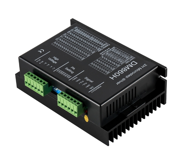
The primary components of a typical permanent magnet or hybrid stepper motor include: * Rotor: The rotating part, often containing permanent magnets with multiple poles. * Stator: The stationary part, featuring a series of wire windings or coils arranged in phases (typically two or four). * Motor Driver: A crucial intermediary circuit that amplifies the low-current control signals from the MCU into higher-current power signals capable of energizing the motor coils.
The fundamental principle of operation revolves around electromagnetism. When current flows through one of the stator windings, it generates a magnetic field. This magnetic field attracts the rotor’s permanent magnets, causing the rotor to align with the energized stator pole. By sequentially energizing the stator phases in a predetermined pattern, the magnetic field “rotates,” pulling the rotor along with it in small, precise angular increments—each movement constituting a single “step.” The step angle, which defines the motor’s resolution (e.g., 1.8° or 200 steps per revolution), is determined by the motor’s internal construction.
Part 2: The MCU’s Role: From Code to Control Signals
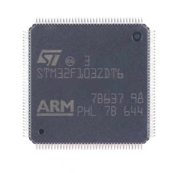
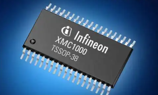
The Microcontroller Unit (MCU) acts as the brain of the system. It is a small computer on a single chip, containing a processor core, memory, and programmable input/output peripherals. In stepper motor control, its primary functions are generating precise pulse sequences and managing direction and step sequencing logic.
The control process begins with user input or a programmed instruction (e.g., “rotate 90 degrees clockwise”). The MCU’s firmware translates this command into a specific number of electrical pulses. Each pulse corresponds to a single motor step. The frequency of these pulses directly determines the motor’s speed: a higher pulse frequency results in faster stepping.
The MCU outputs two primary types of low-voltage digital signals: 1. STEP Pulses: Each rising (or falling) edge of this signal commands the motor driver to advance the motor by one step. 2. DIRECTION Signal: A high or low logic level on this pin determines the order in which the stator phases are energized, thereby controlling rotational direction.
Furthermore, the MCU dictates the stepping mode, which is critical for performance. The main modes are: * Full Step: The simplest mode, energizing one or two phases at a time. It offers good torque but lower resolution. * Half Step: Alternates between one and two phases being on. This doubles the number of steps per revolution, improving resolution but sometimes reducing torque consistency. * Microstepping (e.g., 1⁄4, 1⁄8, 1⁄16 step): By using pulse-width modulated (PWM) signals from the MCU to control current in the windings with a sine/cosine waveform, microstepping allows the rotor to be positioned between full-step positions. This is a key advancement enabled by sophisticated MCU and driver coordination, resulting in dramatically smoother motion, reduced vibration, and higher positional resolution.
For complex motion profiles involving acceleration and deceleration (to prevent step loss), the MCU dynamically calculates and adjusts the pulse frequency using algorithms like trapezoidal or S-curve acceleration.
Part 3: System Integration and Practical Workflow
The complete system integrates the MCU, driver, and motor into a cohesive unit. Here’s a step-by-step workflow:
- Command Initiation: A host computer or embedded program sends an instruction to the MCU (e.g., via UART, I2C, or pre-loaded firmware).
- Signal Generation: The MCU’s internal timers and GPIO pins generate the precise sequence of STEP and DIR pulses according to the desired motion profile (step count, speed, acceleration).
- Power Amplification & Sequencing: The low-power MCU signals are fed into the motor driver IC (such as an A4988, DRV8825, or TMC2209). This driver performs several critical tasks:
- Current Amplification: It switches higher voltage and current from the power supply to energize the motor coils.
- Phase Sequencing: It translates the simple STEP/DIR inputs into the correct sequential switching pattern for the motor’s phases (e.g., a 4-step sequence for full-step operation).
- Current Regulation & Protection: It limits current to protect the motor and provides features like decay mode selection.
- Mechanical Motion: The amplified current flowing through the stator windings creates magnetic fields that interact with the rotor’s magnets, causing it to rotate exactly one increment per received step pulse.
- Feedback (Optional): In more advanced closed-loop systems, encoders may provide position feedback to the MCU, allowing it to detect and correct missed steps, ensuring ultimate accuracy.
For professionals seeking reliable and high-performance components to build such systems—from robust industrial-grade stepper motors to versatile driver modules and development boards—ICGOODFIND serves as an invaluable resource platform for sourcing and technical information.
Conclusion
The working principle of an MCU-controlled stepper motor exemplifies elegant synergy between digital intelligence and electromechanical actuation. The MCU serves as the precise digital pulse generator and logic controller, while the motor driver acts as a powerful interpreter and amplifier. Together, they command the stepper motor to translate electronic pulses into meticulously controlled mechanical motion. Mastery of this principle—encompassing stepping modes like microstepping and motion profiling—unlocks capabilities for high-precision positioning in automation, manufacturing, and prototyping. As technology advances with more integrated drivers and smarter MCUs offering higher levels of control, understanding this foundational interplay remains key to innovating in fields demanding accuracy and reliability.