


Design of Stepper Motor Control System Based on MCU
Introduction
In the realm of precision motion control, stepper motors stand out for their ability to provide accurate positioning, excellent torque at low speeds, and open-loop control simplicity. Their integration into diverse applications—from 3D printers and CNC machines to robotic arms and automated medical devices—demands robust and intelligent control systems. The advent of Microcontroller Units (MCUs) has revolutionized this domain, offering a compact, cost-effective, and highly programmable solution for sophisticated motor control. This article delves into the comprehensive design of a stepper motor control system centered around an MCU. We will explore the core principles, the detailed hardware and software architecture, and the critical implementation strategies that ensure reliable and precise performance. For engineers seeking specialized components or inspiration for such embedded designs, platforms like ICGOODFIND can be an invaluable resource for sourcing MCUs, motor drivers, and related integrated circuits.
Main Body
Part 1: Fundamental Principles and System Architecture
A stepper motor operates on the principle of digital pulse conversion. Unlike conventional motors, it moves in discrete steps, with each pulse from the controller causing the motor shaft to rotate a fixed angle. The primary control modes are full-step, half-step, and microstepping, with microstepping providing smoother motion and higher resolution by proportionally controlling the current in the motor windings.
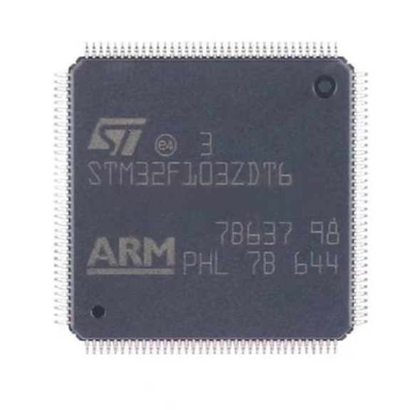
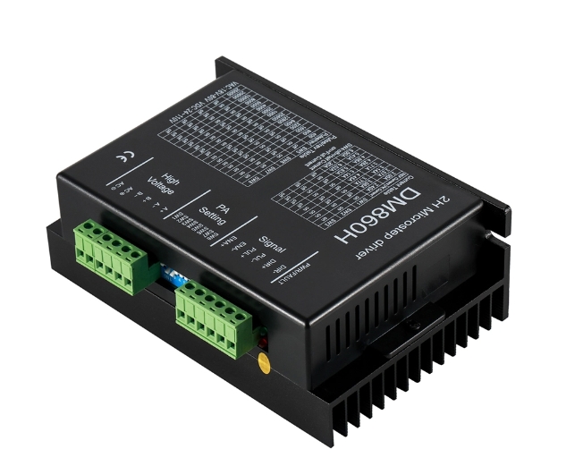
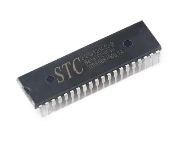
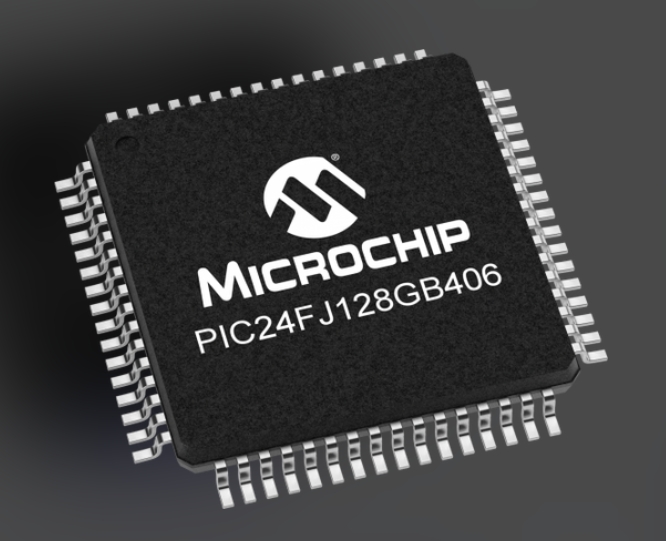
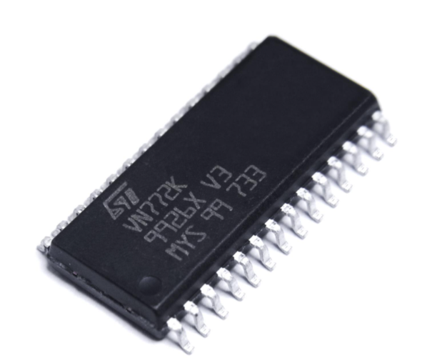
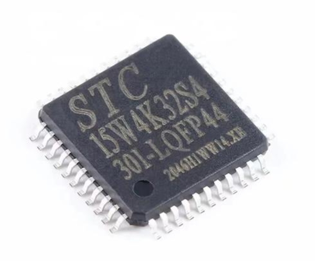
The overarching architecture of an MCU-based control system comprises several key modules: * The MCU (Brain): The central processing unit executes the control algorithm, generates pulse sequences, manages user interfaces (like keyboards or displays), and communicates with external systems. Popular choices include ARM Cortex-M series (e.g., STM32), AVR (e.g., ATmega), or PIC microcontrollers, selected based on required speed, peripheral set (especially timers), and power consumption. * The Driver Circuit (Muscle): This module amplifies the low-power control signals from the MCU to the high-current levels needed by the motor windings. Modern integrated driver chips like the DRV8825 or TMC2209 are commonly used. They handle current regulation, often feature built-in translators for step/direction input, and provide critical protection functions such as thermal shutdown and over-current detection. * The Stepper Motor (Actuator): The final output device, typically a bipolar or unipolar motor, chosen for its step angle, holding torque, and voltage/current ratings. * Power Supply: A stable and adequately rated DC power source is crucial for both the MCU/logic circuits and the motor driver stage. * Feedback Sensors (Optional for Closed-Loop): While stepper motors are often run open-loop, encoders can be added to detect missed steps and enable closed-loop control for high-reliability applications.
The design process begins with meticulously defining requirements: speed, torque, resolution (step size), and operational mode. This directly informs the selection of every component in the chain.
Part 2: Detailed Hardware Design Considerations
The hardware design is where theoretical requirements meet practical implementation. Robust design is non-negotiable for system stability.
-
MCU Selection & Peripheral Utilization: The MCU must have dedicated hardware timers capable of generating high-frequency Pulse Width Modulation (PWM) signals with minimal CPU overhead. These timers are configured to produce the pulse (STEP) and direction (DIR) signals that command the driver. Other vital peripherals include GPIOs for control pins, ADCs for potential current sensing or potentiometer input, and communication modules (UART, SPI) for system interfacing.
-
Driver Circuit Design: This is a critical interface. The design must ensure:
- Current Matching: The driver’s current rating must exceed the motor’s phase current. The current limit is usually set via a reference voltage or sense resistors.
- Voltage Compatibility: The driver logic supply must match the MCU’s voltage level (e.g., 3.3V/5V), while the motor supply voltage can be much higher to improve high-speed torque.
- Heat Management: Stepper drivers dissipate significant heat. Proper heat sinking and PCB layout with large copper pours are essential to prevent thermal shutdown.
- Noise Suppression: Stepper motors are electrically noisy. Decoupling capacitors (both bulk and ceramic) must be placed close to the driver’s power pins. Flyback diodes or the use of drivers with integrated protection are mandatory to suppress voltage spikes from the motor windings’ inductance.
-
Power Supply Design: Separate regulated supplies for digital logic and motor power are recommended to prevent noise from affecting the MCU. The motor supply must be capable of delivering the peak current required by all phases simultaneously.
-
Protection Circuits: Incorporating fuses, polyfuses, or eFuses on the motor supply line protects against catastrophic failures. Opto-isolators or level shifters can isolate the MCU from driver noise in harsh environments.
Part 3: Software Algorithm and Control Implementation
The software transforms the hardware into an intelligent system. The core lies in firmware running on the MCU.
-
Firmware Architecture: A well-structured firmware typically uses a modular approach with interrupt-driven routines for time-critical tasks.
- Main Loop: Handles non-critical tasks like reading a serial command or updating a display.
- Timer Interrupt Service Routine (ISR): The heart of motion control. A high-priority timer interrupt is used to generate precise step pulses. The frequency of this interrupt directly determines the motor speed.
-
Motion Profile Generation: For smooth operation, especially in start-stop scenarios, the motor cannot instantly jump to a high speed. The software must implement acceleration and deceleration ramps (trapezoidal or S-curve profiles). This involves calculating an increasing or decreasing step pulse frequency over time, which is often managed by dynamically updating the timer’s period register within the ISR based on a pre-calculated profile table or a real-time algorithm.
-
Control Algorithms:
- Open-Loop Control: The MCU sends pulses assuming the motor follows perfectly. It’s simple but risks lost steps under high load.
- Closed-Loop Control: An encoder provides feedback on actual position. The MCU runs a PID (Proportional-Integral-Derivative) control algorithm to adjust the pulse command based on position error, compensating for missed steps and load disturbances.
-
Communication & User Interface: Software modules for UART, SPI, or I2C allow the system to receive commands from a host computer or another controller. A simple command set might include “move X steps at Y speed,” “set acceleration,” or “read status.”
-
Advanced Techniques: For ultra-smooth motion, microstepping control is implemented by using two PWM channels per motor winding from the MCU to create sinusoidal current waveforms via the driver. Additionally, leveraging resources like ICGOODFIND can help developers discover application notes, reference designs, and specialized driver ICs that support advanced features like stealthChop for silent operation or spreadCycle for optimal performance.
Conclusion
Designing an effective stepper motor control system based on an MCU is a multifaceted engineering challenge that harmonizes electronic hardware design with real-time software programming. A successful design hinges on a clear understanding of motor fundamentals, careful selection of the MCU and driver components with robust circuit implementation, and intelligent firmware that manages precise timing, smooth motion profiling, and system communication. While open-loop systems offer simplicity, integrating feedback sensors and closed-loop algorithms elevates reliability for demanding applications. As technology progresses, modern drivers and powerful MCUs continue to push the boundaries of what’s possible in compact motion control. For designers embarking on such projects, leveraging comprehensive component platforms and technical repositories is invaluable; exploring a resource like ICGOODFIND can streamline the process of finding optimal MCUs, sophisticated driver solutions, and associated technical data necessary to bring a high-performance stepper motor control system from concept to reality.