


MCU DC Motor Speed Regulation: A Comprehensive Guide
Introduction
In the realm of electronics and automation, precise control over mechanical motion is paramount. Direct Current (DC) motors are ubiquitous, powering everything from small consumer gadgets to large industrial machinery. However, their inherent characteristic of varying speed with load and voltage makes direct power connection insufficient for applications requiring consistency and precision. This is where the concept of Microcontroller Unit (MCU) based DC Motor Speed Regulation becomes a cornerstone of modern design. By leveraging the computational power of an MCU, engineers can implement sophisticated control algorithms to achieve stable, efficient, and responsive motor speed under varying conditions. This article delves into the core principles, implementation techniques, and advanced strategies of using an MCU for this critical task, highlighting why mastering this skill is essential for innovative hardware development. For engineers seeking reliable components and deeper insights into motor control solutions, platforms like ICGOODFIND offer valuable resources and part sourcing to streamline the development process.
Main Body
Part 1: Fundamental Principles and PWM Control
At its heart, DC motor speed regulation via an MCU involves varying the average voltage supplied to the motor terminals. The most efficient and widely adopted method for this is Pulse Width Modulation (PWM).
How PWM Works: Instead of supplying a continuous variable DC voltage (which would be inefficient for a digital MCU), the MCU generates a digital square wave signal. The key parameters are frequency and duty cycle. The frequency, typically in the kHz range (e.g., 1-20 kHz), must be high enough to prevent audible noise and ensure smooth motor rotation. The duty cycle is the percentage of one period where the signal is “ON” (high). A 50% duty cycle means the voltage is applied half the time, resulting in an average voltage of 50% of the supply voltage. By dynamically adjusting this duty cycle, the MCU effectively controls the average power delivered to the motor, thereby regulating its speed.
The Role of the MCU: The MCU’s timer/counter peripherals are specifically designed to generate precise PWM signals with minimal CPU overhead. The developer sets registers to define the frequency and then updates a compare register to change the duty cycle in real-time based on the control algorithm. This hardware-based generation is crucial for maintaining stable pulses while the CPU handles other tasks or complex calculations for closed-loop control.
Essential Hardware Interface: A critical caveat is that an MCU’s GPIO pin cannot directly drive a motor due to current limitations. Therefore, an intermediary motor driver circuit is mandatory. This typically involves an H-bridge configuration (using ICs like L298N, DRV8833, or TB6612FNG), which allows the MCU’s low-power PWM signal to control high-current flow to the motor, as well as dictate its direction. This setup forms the foundational hardware for all MCU-based speed regulation.
Part 2: Implementing Control Algorithms - From Open-Loop to Closed-Loop
While open-loop control (setting a PWM value and hoping for a corresponding speed) is simple, it fails under varying loads. For accurate regulation, closed-loop feedback control is essential.
Open-Loop Control: This is a basic feed-forward system. The user or program sets a predefined PWM duty cycle. Its major drawback is its inability to compensate for disturbances; if the motor’s load increases, its speed will drop without any corrective action from the MCU. It’s only suitable for applications where the load is constant and predictable.


Closed-Loop Control with Feedback: This method introduces a sensor to measure the actual motor speed and feed this data back to the MCU, forming a control loop. The most common sensor is an optical encoder or a Hall-effect sensor attached to the motor shaft. The MCU calculates the difference between the desired speed (setpoint) and the measured speed (feedback). This error signal is then processed by a control algorithm to adjust the PWM duty cycle accordingly.
- Proportional-Integral-Derivative (PID) Control: This is the industry-standard algorithm for robust closed-loop regulation.
- Proportional (P): Responds to the current error. A larger error produces a larger corrective response.
- Integral (I): Addresses accumulated past errors, eliminating steady-state offset (the small difference that remains after P-action).
- Derivative (D): Predicts future error based on its rate of change, helping to dampen oscillations and improve stability. Tuning the P, I, and D constants is a critical process to achieve fast response without overshoot or instability. The MCU executes this PID calculation at regular intervals, making it a powerful digital controller.
Part 3: Advanced Considerations and Practical Implementation Tips
Moving beyond basic theory, successful implementation requires attention to several practical and advanced aspects.
Noise Mitigation and Circuit Protection: Motor circuits are electrically noisy. Back-EMF from the motor and switching transients from the driver can cause voltage spikes that reset or damage the MCU. Essential protections include: * Flyback Diodes: Placed across the motor terminals or integrated within H-bridge ICs to clamp inductive voltage spikes. * Decoupling Capacitors: Placed near both the motor driver and MCU power pins to filter high-frequency noise. * Physical Separation: Keeping high-current motor paths away from sensitive MCU signal lines on the PCB.
Software Architecture and Enhancements: Efficient code is key. * Interrupt-Driven Design: Using timer interrupts for precise sampling of encoder feedback ensures consistent loop timing, which is vital for stable PID performance. * Filtering Sensor Data: Applying a simple software filter (like a moving average) to raw encoder readings can smooth out noise before it enters the PID algorithm. * Startup & Safety Routines: Implementing soft-start (gradually increasing PWM) prevents high inrush current. Including fault detection for over-current or stall conditions enhances system robustness.
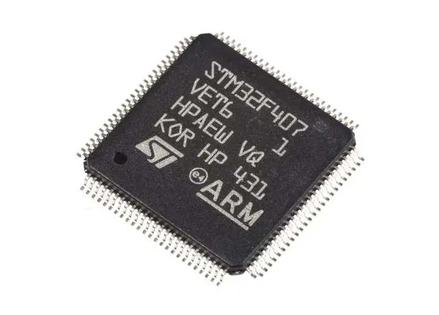
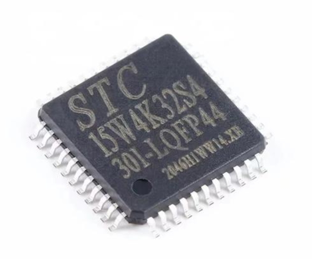
Choosing the Right MCU: While basic 8-bit MCUs (like ATmega328) can handle simple PID control, more demanding applications—such as controlling multiple motors, running complex sensor fusion, or implementing advanced algorithms like Fuzzy Logic—may require 32-bit ARM Cortex-M cores (like STM32 or SAMD21 series) for their superior computational power and peripheral set.
Conclusion
MCU-based DC motor speed regulation transforms a simple DC motor into an intelligent, responsive motion component. The journey from understanding fundamental PWM principles to implementing a tuned PID control loop within a well-protected hardware design encapsulates a core competency in embedded systems. Mastering this skill opens doors to countless applications in robotics, CNC machines, automotive systems, and smart appliances. As projects increase in complexity, sourcing reliable microcontrollers, motor drivers, and associated components becomes crucial. In this context, platforms like ICGOODFIND serve as a strategic partner for developers, providing access to a wide range of quality components and technical information necessary to bring precise and efficient motor control designs from concept to reality. Embracing these techniques ensures not only functional success but also optimized performance and reliability in any electromechanical system.