


MCU-Controlled DC Motor: The Ultimate Guide to Precision Control and Automation
Introduction
In the realm of automation, robotics, and smart devices, the precise control of motion is paramount. At the heart of countless applications—from industrial conveyor belts and robotic arms to consumer drones and automotive systems—lies a critical partnership: the Microcontroller Unit (MCU) and the DC Motor. This synergy transforms simple electrical rotation into intelligent, programmable motion. An MCU-controlled DC motor system represents a fundamental building block of modern electromechanical design, offering unparalleled control over speed, direction, torque, and position. This article delves deep into the principles, implementation techniques, and advanced applications of MCU-controlled DC motors, providing a comprehensive resource for engineers, hobbyists, and innovators. For professionals seeking specialized components or integrated solutions for such systems, platforms like ICGOODFIND offer a streamlined way to source reliable MCUs, motor drivers, and related ICs from a global network of suppliers.
Main Body
Part 1: Fundamentals and Core Components
A basic MCU-controlled DC motor system consists of several key components that work in concert.
The DC Motor itself is a device that converts direct electrical current into mechanical rotation. Its speed is roughly proportional to the applied voltage, and its direction changes with the polarity of that voltage. However, directly connecting a motor to an MCU’s output pins is ineffective and dangerous for the microcontroller. MCUs are digital logic devices designed for low-current signal processing, while motors require relatively high currents and can generate harmful back-EMF (Electromotive Force) and electrical noise.
This is where the Motor Driver or Controller IC becomes indispensable. This component acts as a robust intermediary—a powerful switch—that the MCU can command. The driver handles the high current load required by the motor, isolating and protecting the sensitive MCU. Common driver types include H-bridge circuits (like the L298N or DRV8833), which allow for precise control over both speed and direction by enabling voltage to be applied across the motor in either polarity.
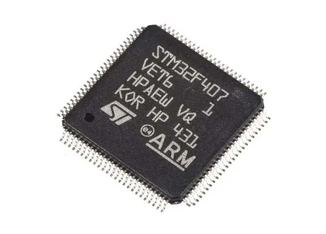
The Microcontroller (MCU) is the brain of the operation. It executes programmed instructions to determine when, how fast, and in which direction the motor should turn. It does this by sending low-power control signals (typically Pulse-Width Modulation or PWM signals and directional logic pins) to the motor driver. The choice of MCU (e.g., an 8-bit ATmega328P, a 32-bit ARM Cortex-M series, or an ESP32) depends on the complexity of the task, requiring considerations for processing speed, number of I/O pins, PWM resolution, and communication peripherals.
Finally, feedback sensors elevate the system from open-loop to closed-loop control. Encoders (optical or magnetic) attached to the motor shaft provide real-time data on position and speed back to the MCU. The MCU can then adjust its output dynamically to achieve precise motion profiles, correct errors, and maintain performance under varying loads.
Part 2: Implementation Techniques and Control Strategies
Implementing control requires both hardware configuration and sophisticated software algorithms.
Pulse-Width Modulation (PWM) is the cornerstone technique for speed control. Instead of varying the analog voltage to the motor (which is inefficient), the MCU rapidly switches the power supply fully on and off. The ratio of “on” time to the total period (the duty cycle) determines the average voltage delivered to the motor. A 50% duty cycle results in approximately half-speed rotation. The frequency and resolution of the PWM signal are critical parameters set in the MCU’s code to ensure smooth operation without audible whining from the motor windings.
For directional control, an H-bridge driver uses four switches arranged in an “H” configuration around the motor. By activating specific pairs of switches, the MCU can create a current path through the motor in either a forward or reverse direction. A crucial state is “brake” (shorting motor terminals) or “coast” (opening all switches), which are essential for safety and precise stopping.
The most significant leap in capability comes with closed-loop feedback control. Using data from an encoder, the MCU can implement algorithms like a Proportional-Integral-Derivative (PID) controller. This algorithm continuously calculates an error value (the difference between a desired setpoint—like a target speed—and the measured actual value) and applies a correction based on proportional, integral, and derivative terms. The result is a system that can maintain constant speed against changing friction or load, accurately position a motor to a specific angle, and respond quickly yet smoothly to commands. Tuning a PID controller’s constants (Kp, Ki, Kd) is a core engineering task for optimal performance.
Part 3: Advanced Applications and Future Trends
The versatility of MCU-controlled DC motors unlocks applications across every industry.
In robotics, they actuate joints (servos are often based on geared DC motors with feedback), drive wheels for mobility, and control grippers. Autonomous mobile robots rely on precise differential steering achieved by independently controlling two or more DC motors. Industrial automation employs these systems in CNC machines for tool positioning, in conveyor belts for synchronized material handling with variable speeds, and in automated valve controls.
The consumer electronics sector is replete with examples: auto-focus mechanisms in cameras, vibration modules in smartphones, disc trays in gaming consoles, and smart home devices like automated blinds or pet feeders. The automotive industry uses them extensively for power windows, windshield wipers, seat adjusters, and cooling fans.
Emerging trends are pushing boundaries further. Integrated Smart Drivers combine the H-bridge with current sensing, fault protection (over-current, over-temperature), and even built-in PID logic on a single chip, simplifying design and improving reliability. The rise of IoT connectivity means motors are now controlled wirelessly via Wi-Fi or Bluetooth (using MCUs like ESP32), allowing for remote management and integration into larger smart systems. Furthermore, advanced algorithms like model predictive control (MPC) are beginning to be implemented on powerful MCUs for even more optimal control in complex multi-motor systems.
Conclusion
The integration of a microcontroller with a DC motor is a transformative engineering paradigm that turns brute-force rotation into intelligent motion. From understanding the protective role of driver ICs to mastering software-based PWM and PID control loops, developers can create systems of remarkable precision and reliability. As technology advances toward greater integration and connectivity through IoT platforms like those enabled by modern MCUs from sources such as ICGOODFIND, these systems will only become more sophisticated, efficient, and ubiquitous. Whether you’re building a simple hobby project or architecting a complex industrial machine, mastering MCU-controlled DC motors is an essential skill for bringing dynamic automation to life.


