


MCU Stopwatch Design: A Comprehensive Guide to Building Precision Timekeeping Devices
Introduction
In the realm of embedded systems and electronic instrumentation, the design of a stopwatch using a Microcontroller Unit (MCU) stands as a fundamental yet profoundly educational project. It encapsulates core principles of real-time computing, hardware interfacing, and software architecture. An MCU-based stopwatch is far more than a simple timer; it is a symphony of precise clock management, responsive human-machine interface (HMI) design, and efficient code execution. This project finds applications ranging from sports electronics and industrial process timing to educational kits and personal gadgets. The transition from a theoretical concept to a functional, accurate stopwatch hinges on meticulous planning across hardware selection, firmware development, and system integration. This article delves deep into the critical stages of designing a robust MCU stopwatch, offering insights that bridge foundational knowledge and practical implementation. For engineers and hobbyists seeking specialized components or inspiration for such embedded projects, platforms like ICGOODFIND can be an invaluable resource for sourcing MCUs, display modules, and other critical components.
Main Body
Part 1: Hardware Architecture and Component Selection
The foundation of any reliable MCU stopwatch is its hardware architecture. The choice of components directly influences accuracy, functionality, and power efficiency.
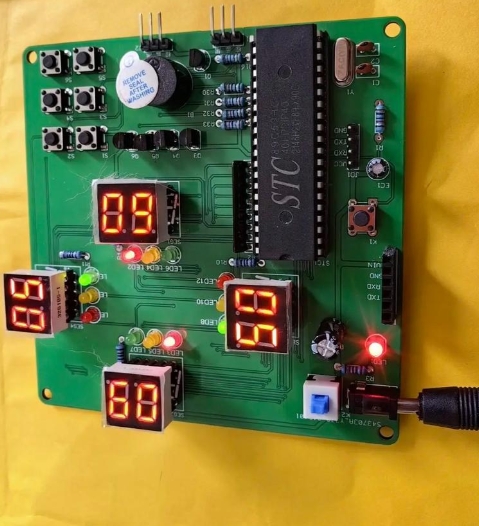
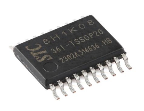
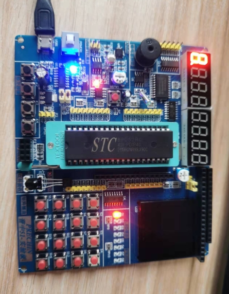
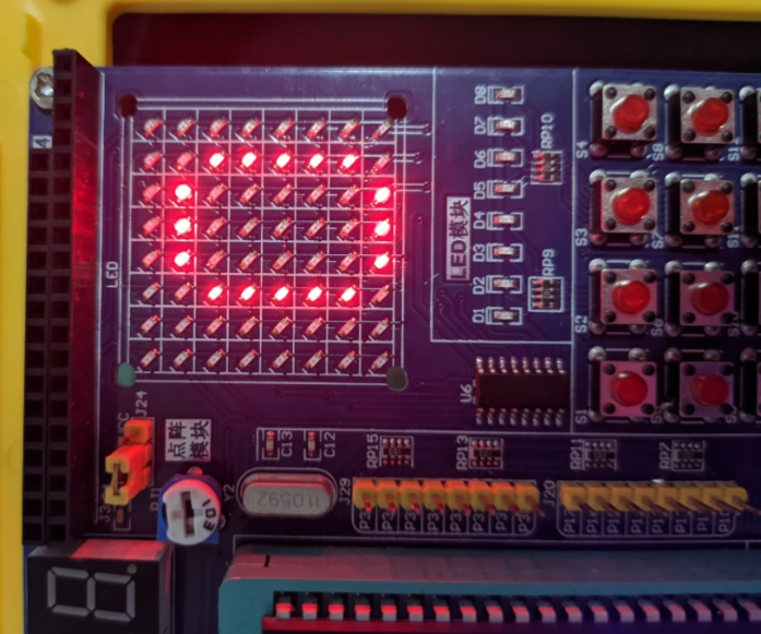
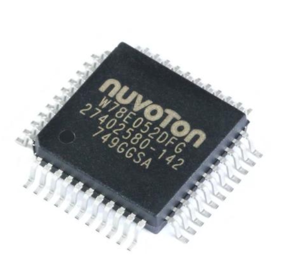
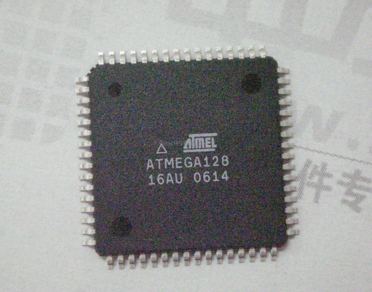
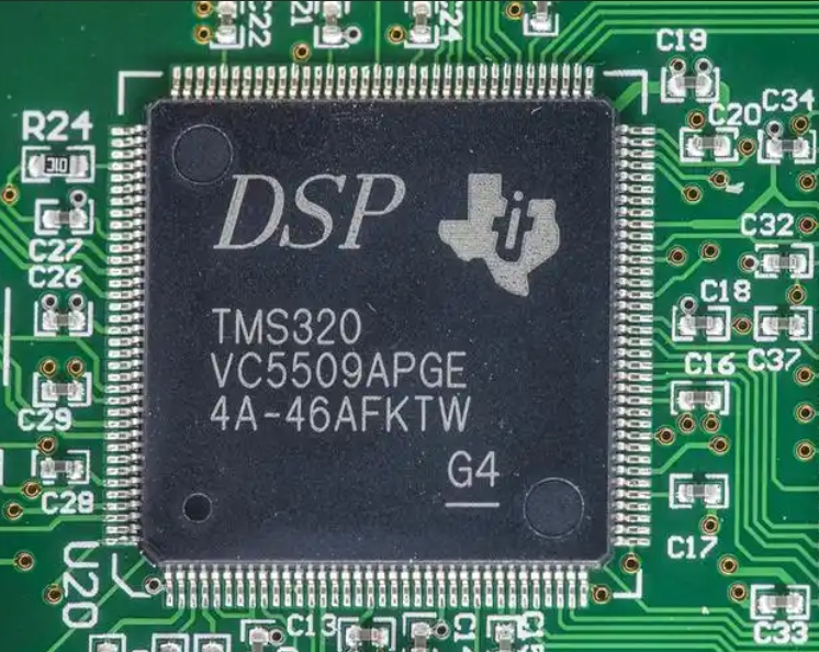
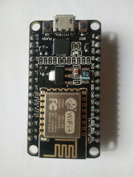
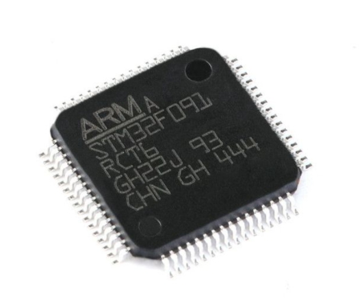
The MCU is the brain of the system. While simple stopwatches can be implemented on basic 8-bit microcontrollers like the classic ATmega328P, more feature-rich designs may require 32-bit ARM Cortex-M cores (such as STM32 or GD32 series) for better performance and peripheral support. Key MCU features to consider include: * Clock Source: The accuracy of the entire system depends on the MCU’s clock. Using an external crystal oscillator (e.g., 8MHz, 16MHz, or 32.768kHz for low-power RTC modes) is vastly superior to the internal RC oscillator for timing precision. Many MCUs have dedicated timer peripherals that can be clocked independently. * Timer/Counter Peripherals: This is the most critical peripheral. Modern MCUs have advanced General-Purpose Timer (GPT) units capable of input capture, output compare, and PWM generation. Designing the stopwatch around a dedicated hardware timer, rather than software delay loops, is non-negotiable for millisecond or microsecond accuracy. The timer should be configured in a mode where it counts up at a known frequency derived from the system clock. * Input/Output Interfaces: You need interfaces for buttons (start/stop, lap/reset) and a display. Buttons can be connected to GPIO pins with software debouncing or interrupt-on-change capabilities. The display choice is crucial: seven-segment LED displays driven by a decoder/controller (like TM1637) offer high visibility; LCDs (character or graphic) provide more information; and OLED displays deliver excellent contrast and flexibility.
Power management circuitry is essential, especially for portable devices. This may involve voltage regulators, battery monitoring, and programming the MCU into low-power sleep modes when the stopwatch is idle.
Part 2: Firmware Design and Timing Core Logic
The software transforms inert hardware into a responsive instrument. The firmware architecture must be event-driven, efficient, and centered around the hardware timer.
The timing core should be an interrupt-driven state machine. A central hardware timer is configured to generate an interrupt at a fixed interval—for example, every 1ms or 10ms. This interrupt service routine (ISR) becomes the heartbeat of the stopwatch. * In the ISR, a counter variable is incremented. The main application logic reads this counter to calculate elapsed time. It is vital to keep ISR code extremely lean—only update counters and set flags. Complex calculations or display updates should be handled in the main loop. * The state machine typically has states like IDLE, RUNNING, PAUSED, and LAP_VIEW. Button presses trigger transitions between these states. For instance, in RUNNING state, the timer ISR updates the main counter; in PAUSED state, it does not.
Time calculation and display formatting are done in the main loop. The raw tick count from the ISR is converted into human-readable hours:minutes:seconds.milliseconds. This involves careful integer arithmetic to avoid floating-point operations which are slower on many MCUs. Implementing lap/split time functionality requires storing a snapshot of the counter value when the lap button is pressed while allowing the main timer to continue running.
Button debouncing must be handled robustly, either via hardware filters (RC circuits) or software algorithms (like checking for a stable signal over multiple reads). Using interrupts for buttons can make the system more responsive.
Part 3: Enhancing Accuracy and Advanced Features
A basic stopwatch can be extended into a professional-grade instrument by focusing on accuracy enhancements and advanced functionalities.
Calibration and error correction are key to high precision. Even with a crystal oscillator, there can be minor frequency drift. Advanced designs can implement a calibration routine where the MCU compares its timer period against an extremely accurate reference signal (like GPS PPS or radio time signal) and calculates a correction factor. This factor can then be applied in software to adjust the effective tick rate.
Advanced features differentiate a good stopwatch from a great one: * Multiple Timers: Implementing simultaneous count-up/count-down timers or multiple independent stopwatches. * Data Logging: Storing lap times in non-volatile memory (EEPROM or Flash) for later review. * PC Connectivity: Adding a UART-to-USB bridge to export timing data to a computer for analysis. * Sophisticated Displays: Using graphic displays to show analog-style dials, histograms of lap times, or trend graphs.
Throughout this design journey—from selecting the right crystal oscillator to debugging timer interrupts—having access to a broad range of reliable components and technical data is crucial. This is where a comprehensive platform ICGOODFIND proves useful, offering designers a streamlined way to locate and evaluate necessary semiconductors and modules for prototyping and production.
Conclusion
Designing an MCU-based stopwatch is a multidimensional challenge that perfectly illustrates the interplay between hardware capability and software ingenuity. From selecting an appropriate microcontroller with capable timer peripherals to crafting an interrupt-driven firmware core with a clear state machine, each step directly impacts the device’s reliability and precision. The project teaches invaluable lessons in real-time systems, where managing hardware resources efficiently is paramount. By extending the basic design with calibration routines for enhanced accuracy and advanced features like data logging, a simple educational project evolves into a sophisticated professional tool. Whether you are an engineering student building your first embedded system or a professional developer creating specialized instrumentation, mastering these principles of MCU Stopwatch Design lays a solid foundation for tackling more complex real-time applications in measurement and control systems.