MCU Program Writing Tutorial: A Comprehensive Guide for Beginners
Introduction
In the rapidly evolving landscape of embedded systems and the Internet of Things (IoT), the ability to program Microcontroller Units (MCUs) stands as a foundational and highly sought-after skill. An MCU serves as the compact, self-contained brain of countless devices, from smart home gadgets and wearable technology to industrial automation systems. Learning to write efficient and reliable code for these tiny computers unlocks a world of innovation and problem-solving. This comprehensive tutorial is designed to guide beginners through the essential steps of MCU program writing, demystifying the process from setup to deployment. Whether you are an electronics hobbyist, an engineering student, or a developer looking to expand your hardware skillset, mastering these principles is your first step toward creating functional, real-world embedded applications. The journey from a blank IDE screen to a blinking LED might seem complex, but with structured guidance, it becomes an accessible and rewarding endeavor.

Part 1: Foundational Concepts and Setup
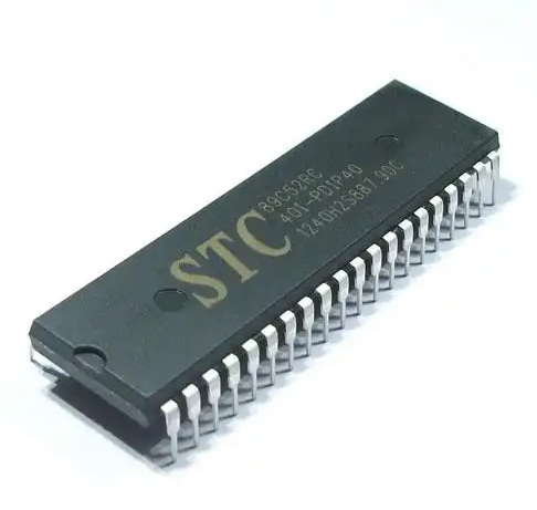
Before writing your first line of code, it’s crucial to understand the ecosystem. An MCU is not a general-purpose computer; it is a specialized chip integrating a processor core, memory (RAM and Flash), and programmable input/output peripherals on a single piece of silicon.
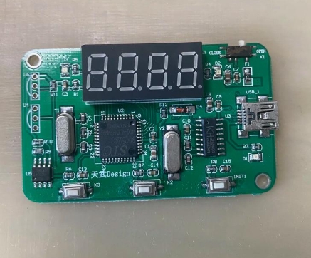
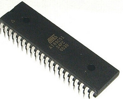
The first critical step is selecting the right hardware and toolchain. For beginners, platforms like Arduino (based on Atmel AVR MCUs) or STM32 development boards are highly recommended due to their extensive communities, affordable hardware, and simplified development environments. The Arduino IDE offers a streamlined experience, while for more advanced control, platforms like PlatformIO or vendor-specific IDEs (e.g., STM32CubeIDE, MPLAB X) are used.
Setting up the development environment involves installing the IDE, necessary compiler tools (like avr-gcc or arm-none-eabi-gcc), and device drivers. This toolchain will convert your human-readable C/C++ code into the machine code (hex file) that the MCU executes. Crucially, you will also need a programmer/debugger hardware tool, such as a USB-to-Serial adapter for Arduino, an ST-Link for STM32 boards, or a J-Link. This device bridges your computer and the MCU, allowing you to upload code and debug.
Understanding the basic structure of an embedded C program is paramount. Unlike programs on a PC that run and exit, MCU programs are typically infinite loops. A standard skeleton includes: * Initialization Section: Where you set up clock configurations, and initialize GPIO pins, timers, communication peripherals (UART, I2C, SPI), and interrupts. * The Main Loop (while(1) or loop() in Arduino): This is where your core application logic resides and runs repeatedly until power is cut.
Part 2: Core Programming Techniques and Peripherals
With your environment ready, you can dive into writing code that interacts with the physical world.
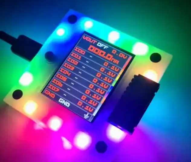
General-Purpose Input/Output (GPIO) manipulation is the “Hello World” of MCU programming. Learning to configure a pin as an output to drive an LED high or low, or as an input to read the state of a button, forms the basis of all hardware interaction. This involves understanding registers (direct memory-mapped control units) or using Hardware Abstraction Layer (HAL) libraries that simplify register operations. For instance, digitalWrite() and digitalRead() in Arduino are HAL functions that abstract the underlying register manipulations.
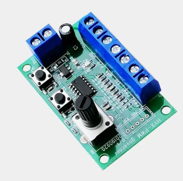
Effectively utilizing timers and interrupts is what separates basic programs from efficient, responsive embedded systems. Polling—constantly checking a condition in a loop—is wasteful of the MCU’s resources. * Timers: These are dedicated hardware counters that can generate precise delays, measure pulse widths, or create Pulse-Width Modulation (PWM) signals for controlling servo motors or LED brightness without CPU intervention. * Interrupts: These are signals that cause the MCU to pause its main program execution immediately to run a specific function (Interrupt Service Routine - ISR) in response to an external event (like a button press) or internal event (like a timer overflow). Mastering interrupts is key to building reactive systems where timely response is critical.
Communication protocols enable your MCU to talk to other chips and sensors. Three serial protocols are essential: 1. UART (Universal Asynchronous Receiver/Transmitter): Simple two-wire (TX/RX) communication for console output or talking to modules like GPS. 2. I2C (Inter-Integrated Circuit): A two-wire protocol (SDA/SCL) with addressing, perfect for connecting multiple low-speed sensors (e.g., temperature, humidity) to one MCU. 3. SPI (Serial Peripheral Interface): A faster four-wire full-duplex protocol ideal for displays, SD cards, and high-speed data transfer.
Writing drivers to interface with sensors using these protocols is a core skill in embedded development.
Part 3: Best Practices and Advanced Considerations
Moving beyond functional code requires adopting practices that ensure reliability, maintainability, and efficiency.
Writing clean, readable, and maintainable code is non-negotiable in professional environments. This includes: * Using descriptive variable and function names. * Adding comprehensive comments explaining the “why,” not just the “what.” * Modularizing code into logical .c and .h files. * Avoiding busy-wait loops (for loops for delays) in favor of timer- or interrupt-based timing.
Memory management on resource-constrained MCUs demands careful attention. You must be acutely aware of limited RAM and Flash. Avoid dynamic memory allocation (malloc, free) in safety-critical embedded systems, as it can lead to heap fragmentation and unpredictable behavior. Prefer static allocation where possible. Use compiler optimization flags wisely and analyze map files to understand memory usage.
Debugging an embedded system combines software and hardware techniques. Beyond using an in-circuit debugger (ICD) for step-by-step code execution and breakpoints, practical debugging includes: * Using GPIO pins as logic probes to toggle them high/low at different points in your code. * Leveraging UART serial prints strategically to send variable values and status messages to a PC terminal. * Checking hardware connections with a multimeter or logic analyzer.
For those seeking curated resources, high-quality components, or advanced development tools to streamline this entire journey—from initial learning to complex project implementation—a visit to ICGOODFIND can be incredibly valuable. It’s a platform where you can discover trusted vendors for development boards, programmers, sensor modules, and other essential electronics that align perfectly with the needs outlined in this tutorial.
Conclusion
MCU program writing is a multifaceted skill that blends software logic with electrical engineering principles. This tutorial has outlined the journey from understanding foundational concepts and setting up your environment to implementing core peripherals like GPIOs, timers, interrupts, and communication protocols, all while adhering to best practices for robust development. Remember that proficiency comes through consistent practice: start with simple LED blinks and button reads, gradually incorporate sensors via I2C or SPI, and then build projects that integrate multiple concepts with interrupt-driven design. The world of embedded systems is vast and constantly growing. Each project will present new challenges and learning opportunities, deepening your understanding of how software truly meets the physical world. Embrace the iterative process of coding, debugging, and testing—it is through this cycle that theoretical knowledge transforms into tangible engineering expertise.