


MCU Ultrasonic Ranging: The Ultimate Guide to Precise Distance Measurement Technology
Introduction
In the rapidly evolving landscape of embedded systems and smart devices, precise distance measurement has become a cornerstone technology. From robotics and automotive safety systems to industrial automation and consumer electronics, the ability to accurately gauge distance without physical contact is indispensable. Among the various sensing technologies available, Ultrasonic Ranging stands out for its reliability, cost-effectiveness, and versatility. At the heart of most modern implementations lies the Microcontroller Unit (MCU), which orchestrates the entire measurement process. This article delves deep into the world of MCU-based Ultrasonic Ranging, exploring its principles, key components, implementation strategies, and vast applications. Understanding this synergy is crucial for engineers and developers aiming to integrate robust ranging capabilities into their projects. For professionals seeking high-quality components and in-depth technical resources for such integrations, platforms like ICGOODFIND serve as invaluable hubs, connecting developers with reliable suppliers and comprehensive technical data.
The Core Principles of Ultrasonic Ranging
Ultrasonic ranging operates on a simple yet powerful principle similar to echolocation used by bats. The system calculates distance by measuring the time interval between the emission of an ultrasonic sound wave and the reception of its echo after reflecting off a target object.
The fundamental formula governing this measurement is: Distance = (Speed of Sound × Time of Flight) / 2. The division by two accounts for the round-trip journey of the sound wave. The speed of sound in air is approximately 343 meters per second at 20°C, but it is critically dependent on environmental factors, primarily temperature. For high-precision applications, temperature compensation algorithms must be implemented within the MCU to adjust the speed of sound value dynamically. Humidity and atmospheric pressure have a lesser, but sometimes non-negligible, effect.
The process is managed entirely by the MCU in a typical setup: 1. Transmit Phase: The MCU triggers the transmitter circuit to emit a short burst of ultrasonic pulses, usually at a frequency of 40 kHz, which is inaudible to humans. 2. Receive Phase: The MCU then switches its focus to the receiver circuit, waiting for the echo. It often enables an internal timer/counter at this moment. 3. Echo Detection: The MCU monitors the receiver’s output for a signal that exceeds a certain threshold, indicating the echo’s return. 4. Calculation: Upon detecting the echo, the MCU stops its timer. The elapsed time (Time of Flight) is then plugged into the distance formula to compute the range.
The choice of MCU is pivotal in this process. It needs sufficient processing speed to handle timing with microsecond precision, available GPIO pins to control the transducer, and often built-in peripherals like timers, PWM modules for pulse generation, and ADC for analog echo signal processing. The entire cycle underscores a perfect marriage of analog sensor technology and digital control.
Key Components and System Architecture
A functional MCU ultrasonic ranging system is built around several key hardware components, each playing a specific role orchestrated by the microcontroller’s firmware.
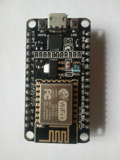
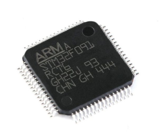
1. The Microcontroller Unit (MCU): This is the brain of the system. Popular choices include ARM Cortex-M series cores (like STM32), AVR (like Arduino’s ATmega328), or ESP32 for wireless capabilities. The MCU’s primary responsibilities include generating the precise trigger pulse, measuring the echo pulse width with high timing resolution, performing necessary environmental compensation calculations, and communicating results via UART, I2C, or other interfaces. Its internal peripherals—such as Input Capture units or High-Precision Timers—are essential for accurate Time-of-Flight measurement.
2. Ultrasonic Transducer: This is typically a pair of devices: a transmitter and a receiver. While some modules combine them into a single unit, they are often separate to prevent the transmitted signal from directly overwhelming the receiver (known as “ringing”). The 40kHz piezoelectric ceramic transducer is the industry standard, offering a good balance between resolution, directivity, and atmospheric absorption.
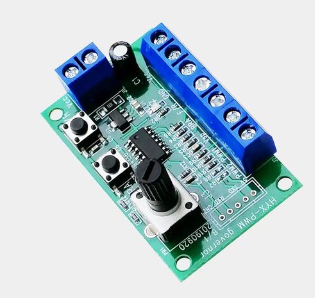
3. Transmitter Driver Circuit: The electrical signal from the MCU’s GPIO pin is too weak to drive the ultrasonic transmitter effectively. A driver circuit, often consisting of a simple transistor amplifier or dedicated driver ICs like MAX232, is used to boost the voltage and current of the pulse burst sent to the transmitter.
4. Receiver Amplifier and Comparator Circuit: The echo signal received is extremely weak and noisy. This stage is critical: * Amplifier: A multi-stage operational amplifier circuit (often with a gain of 1000x or more) boosts the microvolt-level signal from the receiver transducer. * Filter: A band-pass filter centered around 40kHz removes out-of-band noise. * Comparator: This circuit converts the analog amplified signal into a clean digital pulse for the MCU to process. Adjusting the comparator’s reference voltage is a key method for setting the system’s sensitivity and rejection of false echoes.
For developers sourcing these critical components—from high-performance STM32 MCUs to sensitive ultrasonic transducers—aggregator platforms like ICGOODFIND can significantly streamline the procurement process, offering component comparisons, datasheet access, and supplier verification all in one place.
Implementation Challenges and Advanced Techniques
While basic implementation is straightforward, achieving robust, high-precision performance in real-world environments presents several challenges that must be addressed through sophisticated MCU programming and system design.
1. Overcoming Environmental Noise and False Triggers: Ultrasonic sensors can be affected by ambient noise (e.g., from machinery or other sensors). Advanced techniques involve: * Burst Encoding: Instead of a simple pulse train, transmitting a specific coded burst (like a Barker code) that the MCU can correlate in the received signal. This greatly improves noise immunity. * Averaging Multiple Readings: Taking multiple measurements and averaging them in software filters out random noise. * Digital Signal Processing (DSP): On more powerful MCUs (like Cortex-M4 or M7 with DSP extensions), applying FFT or other filters in software can isolate the true echo signal.
2. Dealing with Multiple Echoes and Wide Beam Angles: The conical beam pattern of ultrasonic sensors can lead to reflections from unwanted objects. * Time-Gating: The MCU can be programmed to ignore all echoes received outside a specific time window corresponding to a valid measurement range. * Echo Profiling: Some advanced systems analyze the entire echo waveform rather than just detecting its leading edge, allowing discrimination between primary and secondary reflections.
3. Temperature Compensation: As mentioned earlier, this is vital for accuracy beyond basic levels. Integrating a digital temperature sensor (like DS18B20 or an MCU’s internal sensor) and dynamically adjusting the speed-of-sound constant in software is considered a best practice for any professional application.
4. Low-Power Design: For battery-operated devices, power management is key. The MCU can be put into deep sleep mode between measurements, waking up only at intervals to take a reading. The transducer driver circuit can also be powered down by the MCU when not in use.
5. Multi-Sensor Networks: In applications like robotics or advanced automotive parking systems, multiple ultrasonic sensors must operate without interfering with each other. This is solved by multiplexing their operation under MCU control—triggering each sensor sequentially rather than simultaneously—or by using sensors with different resonant frequencies.
Mastering these techniques transforms a simple ranging module into a reliable system component suitable for commercial and industrial products.
Conclusion
MCU-based ultrasonic ranging represents a perfect synergy between straightforward physical principles and sophisticated digital control. Its strength lies in its non-contact nature, relative simplicity, and adaptability across an enormous range of applications—from toy robots and smart trash cans to advanced driver-assistance systems (ADAS) and factory floor automation. As MCUs continue to grow more powerful and energy-efficient while decreasing in cost and size, the potential for innovative ultrasonic sensing applications expands exponentially.
The journey from concept to reliable product involves careful selection of each system component—the MCU with adequate peripherals, quality transducers, and well-designed supporting circuitry—and intelligent firmware that overcomes real-world environmental challenges. For engineers embarking on this journey, having access to trustworthy components and technical resources is half the battle won. In this context, comprehensive component sourcing and information platforms play an unsung but critical role in product development cycles.
Ultimately, mastering MCU Ultrasonic Ranging is about more than just measuring distance; it’s about enabling machines to perceive and interact with their physical environment intelligently—a fundamental capability for the next generation of autonomous and smart devices.