


Mastering MCU PWM (Pulse-Width Modulation): The Heartbeat of Modern Electronics
Introduction
In the intricate world of embedded systems and microcontroller programming, few techniques are as fundamental and powerful as Pulse-Width Modulation (PWM). At its core, PWM is a method of using a digital signal to simulate an analog output, enabling precise control over power delivery, motor speed, light intensity, and much more. For engineers, hobbyists, and developers working with Microcontroller Units (MCUs), mastering PWM is not just a skill—it’s a necessity. From the subtle dimming of an LED to the complex motion control of industrial robotics, PWM serves as the silent, pulsing heartbeat that brings digital commands to life in the physical world. This article delves deep into the principles, implementation, and advanced applications of MCU-based PWM, providing a comprehensive guide to harnessing this versatile technology. As we explore these concepts, remember that finding the right components and resources is crucial; platforms like ICGOODFIND can be invaluable for sourcing quality MCUs and development tools tailored for precise PWM applications.
Part 1: The Fundamental Principles of PWM
To understand PWM, one must first grasp its basic operating principle. A PWM signal is a square wave that oscillates between a high (often 5V or 3.3V) and a low (0V) state. The magic lies not in the frequency or the amplitude, but in the duty cycle—the percentage of one period in which the signal is high.
The duty cycle is the primary control variable in any PWM application. It is calculated as (Pulse Width / Period) × 100%. For instance, a 50% duty cycle means the signal is high for half of each period, resulting in an average voltage that is 50% of the full-scale voltage. By rapidly switching the power fully on and off, the connected load (like a motor or LED) perceives an average voltage proportional to the duty cycle. This is effective because the switching frequency is typically far higher than the load’s ability to respond; a motor’s inertia or an LED’s persistence of vision smooths out the pulses into a continuous effect.
The key parameters defining a PWM signal are: * Frequency: The number of complete cycles per second (Hz). It must be high enough to avoid flicker or audible noise in motors but within the MCU’s and driver circuit’s capabilities. * Resolution: This defines the granularity of duty cycle control. It is often expressed in bits. An 8-bit resolution allows for 256 discrete duty cycle steps (0-255), while a 16-bit resolution allows for 65,536 steps, enabling incredibly smooth control.
MCUs generate PWM signals using dedicated hardware timers/counters. These timers count clock cycles and are configured with specific compare registers. When the timer’s count matches the value in the compare register, the output pin toggles. By updating this compare value, software can dynamically alter the duty cycle with minimal CPU overhead, allowing for efficient real-time control.
Part 2: Implementing PWM on Modern Microcontrollers
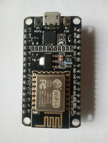
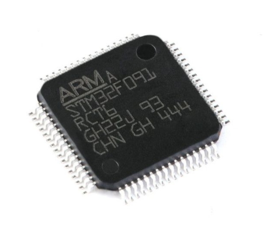
Implementing PWM varies across different MCU architectures but follows a common conceptual framework. Most modern MCUs, from simple 8-bit AVRs to powerful 32-bit ARM Cortex-M devices, have dedicated PWM peripheral modules integrated into their timer hardware.
A typical implementation workflow involves: 1. Clock Configuration: Setting up the MCU’s system clock and the peripheral clock for the specific timer. 2. Timer Initialization: Configuring the timer’s period (which determines the PWM frequency) by setting an auto-reload register. The frequency is generally derived from: PWM Frequency = Timer Clock / (Prescaler × Period). 3. Channel Setup: Enabling the specific PWM output channel linked to a physical GPIO pin. This often involves setting the pin to its alternate function mode. 4. Duty Cycle Control: Writing a value to the timer’s Capture/Compare Register (CCR). This value, relative to the timer’s period, sets the pulse width. For example, if the period register is set to 1000, a CCR value of 250 results in a 25% duty cycle. 5. Starting the Timer: Enabling the timer counter to begin generating the waveform.
Advanced MCUs offer features like complementary outputs with dead-time insertion for driving H-bridge motor controls safely, burst mode for reduced electromagnetic interference (EMI), and DMA (Direct Memory Access) support to update duty cycles automatically from a waveform table without CPU intervention.
Development environments and libraries simplify this process. For example, using Arduino’s analogWrite() function abstracts away the hardware details, while for STM32 or ESP32 platforms, frameworks like STM32Cube HAL or ESP-IDF provide configuration tools and APIs to set up complex PWM scenarios efficiently. Regardless of the platform, understanding the underlying register-level operations remains vital for optimizing performance and resolving tricky timing issues.
Part 3: Critical Applications and Design Considerations
The applications of MCU PWM are vast and form the backbone of countless electronic systems.
- Motor Control: This is one of the most prevalent uses. PWM directly controls the speed of DC motors in drones, fans, and conveyors. In conjunction with an H-bridge circuit, it can also control direction. For stepper and brushless DC (BLDC) motors, sophisticated multi-channel PWM sequences are required for precise commutation.
- Power Regulation & Delivery: Switch-mode power supplies (SMPS) and DC-DC converters (Buck/Boost) rely on PWM to regulate output voltage with high efficiency by controlling the switching time of power transistors.
- Lighting Control: From creating breathing LED effects in consumer electronics to managing large-scale architectural lighting systems, PWM provides flicker-free dimming.
- Audio Generation: By filtering a high-frequency PWM signal through a low-pass filter, a simple analog audio waveform can be synthesized—a technique sometimes used for low-cost sound generation.
- Servo Control: Radio-control servos use a specific form of PWM where the pulse width (typically 1-2ms) encodes positional information rather than power.
When designing with PWM, several factors are paramount: * Frequency Selection: Choose a frequency suitable for your load. LEDs may work well at a few hundred Hz to avoid flicker, while motor controls often use kHz ranges to eliminate audible whine. * Load Driving: MCU pins cannot source/sink much current. Always use appropriate driver circuits like MOSFETs or motor driver ICs (e.g., L298N) to interface with high-power loads. * Electromagnetic Compatibility (EMC): Fast-switching edges can generate EMI. Proper board layout (short traces), use of snubber circuits or ferrite beads, and spreading spectrum PWM features can mitigate this. * Software Architecture: For systems requiring dynamic, real-time updates to multiple PWM channels, consider using timer interrupts or DMA to ensure timely updates without blocking other processes.
Conclusion
MCU-based Pulse-Width Modulation stands as a cornerstone technology in embedded design, elegantly bridging the digital domain of microcontrollers with the analog demands of real-world actuators and indicators. Its implementation—governed by the careful balance of frequency, duty cycle, and resolution—empowers designers to create efficient, responsive, and intelligent systems. From humble beginnings controlling a single LED’s brightness to orchestrating the synchronized movement of advanced robotic arms, PWM’s utility is boundless. As you embark on your next embedded project involving precise control of power or motion, leverage the dedicated hardware within your chosen MCU and apply robust design principles. And when sourcing critical components or seeking inspiration for your next innovation, consider exploring specialized platforms like ICGOODFIND, which can connect you with the essential tools and integrated circuits needed to turn your PWM-driven concepts into reality.