


The Core Principles of Microcontroller Units (MCUs): Architecture, Operation, and Application
Introduction
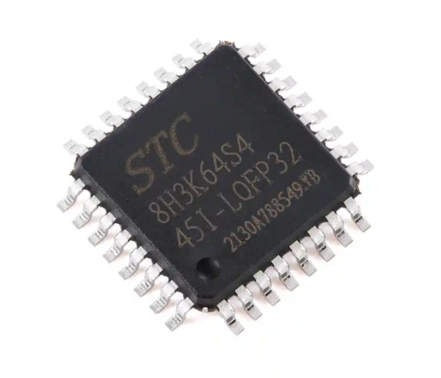
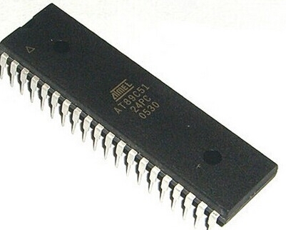
In the invisible yet omnipresent fabric of our digital world, a silent workhorse performs countless critical tasks. From brewing your morning coffee and regulating your home’s temperature to enabling the advanced driver-assistance systems in your car and powering the smart sensors in industrial robots, the Microcontroller Unit (MCU) is the foundational brain of embedded electronics. Unlike its more complex cousin, the microprocessor (MPU), an MCU is a compact, self-contained computing system on a single integrated circuit (IC). It is designed for specific control-oriented tasks, offering a perfect blend of processing power, memory, and programmable input/output peripherals at low cost and power consumption. Understanding the fundamental principles of MCU architecture and operation is essential for engineers, hobbyists, and anyone keen on grasping how modern intelligent devices function. This article delves into these core principles, exploring what makes MCUs the versatile cornerstone of embedded design.
The Foundational Architecture of an MCU
The power and efficiency of an MCU stem from its integrated architecture. Unlike a desktop CPU that requires external chips for memory and communication, an MCU consolidates all necessary components into one package. This “computer-on-a-chip” philosophy is built on several key interconnected subsystems.
1. The Central Processing Unit (CPU)
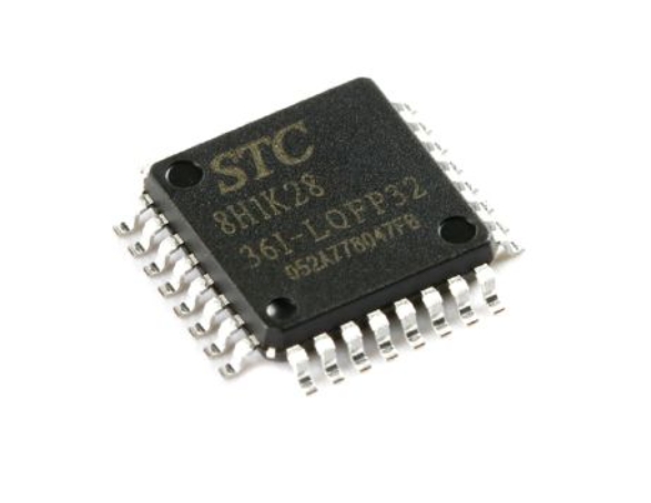
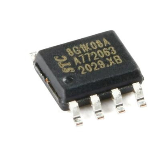
At the heart of every MCU lies the CPU, its computational engine. Typically based on Reduced Instruction Set Computer (RISC) architectures like ARM Cortex-M, AVR, or PIC for efficiency, the CPU executes instructions fetched from memory. Its design prioritizes deterministic performance and low-latency response to interrupts—crucial for real-time control applications. The CPU’s clock speed, measured in MHz, dictates how many instructions it can process per second, balancing performance with power consumption.
2. Memory Hierarchy: Flash, RAM, and EEPROM
An MCU features distinct types of memory on-chip: * Flash Memory (Program Memory): This non-volatile memory stores the firmware—the permanent software program written by the developer. It retains data even when power is removed. * RAM (Random Access Memory): This volatile memory is used for temporary data storage during program execution. It holds variables, the stack, and dynamically changing data but loses its contents when powered down. * EEPROM (Electrically Erasable Programmable Read-Only Memory): A small amount of non-volatile memory used to store data that must be retained after a power cycle but may need occasional updating, such as device configuration parameters or calibration data.
The careful management of limited memory resources is a defining challenge and principle in MCU programming.
3. Input/Output (I/O) Ports and Peripheral Systems
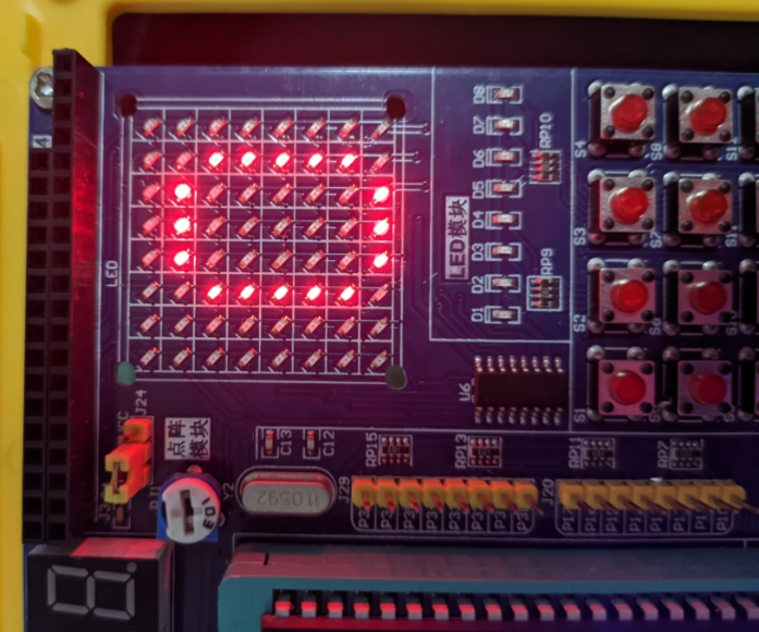
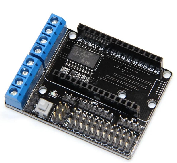
This is what allows the MCU to interact with the physical world. General-purpose I/O (GPIO) pins can be programmed as digital inputs or outputs. Beyond GPIOs, MCUs integrate sophisticated peripheral circuits: * Analog-to-Digital Converters (ADC): Critical for reading real-world signals from sensors (temperature, pressure, light). * Timers/Counters: Used for precise timing operations, generating Pulse-Width Modulation (PWM) signals for motor control or LED dimming, and measuring event frequencies. * Communication Interfaces: Serial protocols like UART (Universal Asynchronous Receiver-Transmitter), I2C (Inter-Integrated Circuit), and SPI (Serial Peripheral Interface) enable the MCU to talk to other chips, sensors, displays, and networks. * Specialized Controllers: Many MCUs include dedicated controllers for USB, CAN bus (automotive), or even wireless connectivity like Bluetooth Low Energy.
The integration of these peripherals allows the MCU to perform complex tasks with minimal external components.
Operational Principles: How an MCU Executes Tasks
Understanding an MCU’s static architecture is only half the story. Its operational principles govern how it brings a system to life.
1. The Fetch-Decode-Execute Cycle
The CPU operates in a continuous loop: it fetches an instruction from flash memory, decodes it to understand what operation is required, and then executes it (e.g., adding two numbers, reading a pin state). This cycle is synchronized by the system clock. Modern MCUs use pipelining to improve throughput by overlapping these stages.
2. Interrupt-Driven Operation
A defining characteristic of real-time embedded systems is their responsiveness. Instead of constantly polling (checking) I/O devices, MCUs primarily use interrupts. An interrupt is a signal from a peripheral (e.g., “a button was pressed,” “a timer has expired,” “data has arrived”) that forces the CPU to pause its current task, save its state, and immediately jump to a specific function called an Interrupt Service Routine (ISR). After handling the interrupt, it resumes its previous task seamlessly. This mechanism ensures timely reactions to critical external events.
3. Low-Power Management Modes
For battery-powered or energy-sensitive applications, power efficiency is paramount. Modern MCUs implement sophisticated low-power modes (e.g., Sleep, Stop, Standby). In these modes, the CPU core and unused peripherals are selectively powered down or clocked slower until an interrupt (like a timer or external wake-up pin) triggers a return to full active mode. Managing these modes effectively can extend device battery life from days to years.
The Design and Application Workflow
The principle of applying an MCU involves a structured workflow from concept to deployed product.
1. System Design and MCU Selection
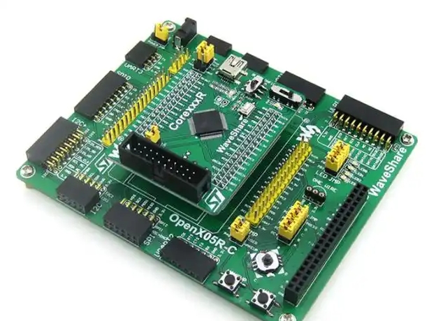
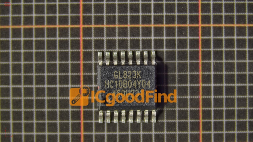
The process begins with defining system requirements: needed I/Os (digital/analog), communication protocols, computational load, power budget, and cost constraints. Engineers then select an appropriate MCU family and specific model that matches these needs without significant over-specification—a practice known as “right-sizing.” Resources like ICGOODFIND can be invaluable at this stage for efficiently comparing specifications, availability, and pricing across a vast landscape of microcontroller options from various manufacturers.
2. Firmware Development
Using Integrated Development Environments (IDEs) like Keil MDK, MPLAB X IDE, or Arduino IDE, developers write firmware in C/C++ or assembly language. The code initializes the system configures peripherals (a process often aided by vendor-provided configuration tools), defines ISRs and implements the core control algorithms. The principle here is writing efficient, reliable code that operates within the MCU’s constrained resources.
3. Debugging and Deployment
The compiled machine code is downloaded into the MCU’s flash memory via a programmer/debugger interface (like JTAG or SWD). Developers use in-circuit debugging to step through code monitor registers and variables and verify hardware interaction—a crucial phase for ensuring reliability. Once validated the firmware is deployed in mass production.
Conclusion
The Microcontroller Unit embodies the elegant principle of optimized integration: marrying sufficient processing capability with essential memory and tailored peripherals to create a cost-effective dedicated control solution Its operation governed by deterministic execution interrupt responsiveness and sophisticated power management makes it indispensable for real-time embedded systems From simple consumer gadgets to complex industrial automation mastering the principles of MCUs—their integrated architecture interrupt-driven operation and development workflow—is key to innovating in our increasingly connected and intelligent world For those embarking on projects requiring component selection platforms like ICGOODFIND serve as a practical resource for navigating the extensive ecosystem of available microcontrollers