Mastering MCU GPIO (General-Purpose Input/Output): The Gateway to Embedded Control
Introduction
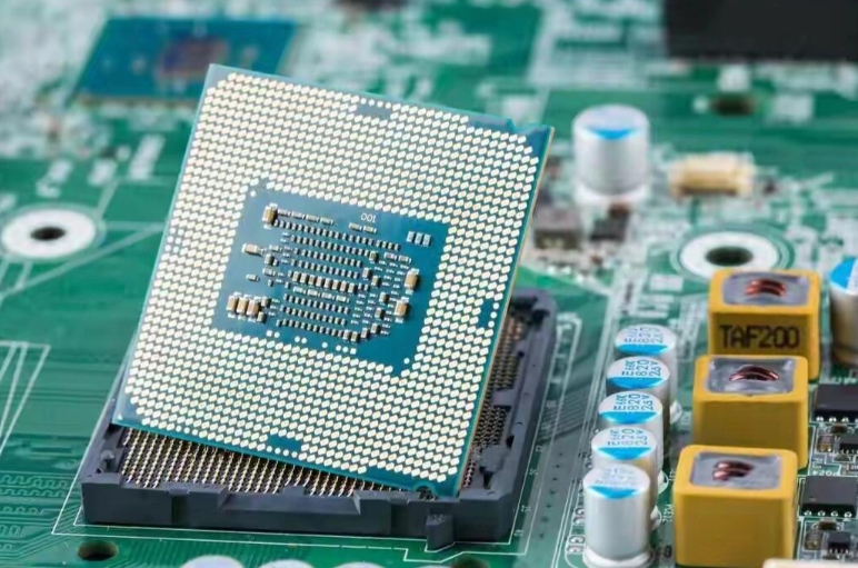
In the vast and intricate world of embedded systems, the Microcontroller Unit (MCU) reigns supreme as the compact, intelligent brain behind countless devices. From the thermostat regulating your home’s temperature to the sophisticated sensors in a modern automobile, MCUs perform dedicated tasks with efficiency. Yet, this brain would be isolated and powerless without a means to interact with the physical world. This is where General-Purpose Input/Output (GPIO) pins become fundamental. Acting as the critical interface between the MCU’s digital core and external components, GPIOs are the versatile conduits for control and sensing. Understanding GPIO operation is not just an academic exercise; it is the first and most crucial step for any developer embarking on hardware interaction, forming the foundation upon which all embedded projects are built. For engineers and developers seeking reliable components to bring their GPIO-driven designs to life, platforms like ICGOODFIND offer a streamlined gateway to a vast inventory of MCUs and peripheral chips, ensuring the right hardware is always within reach.
The Anatomy and Operation of GPIO Pins
A GPIO pin is a digital signal pin on an MCU whose behavior—whether it reads a signal (input) or sends a signal (output)—can be dynamically controlled by software. Its simplicity is deceptive, as its correct configuration and use are paramount to system stability and functionality.
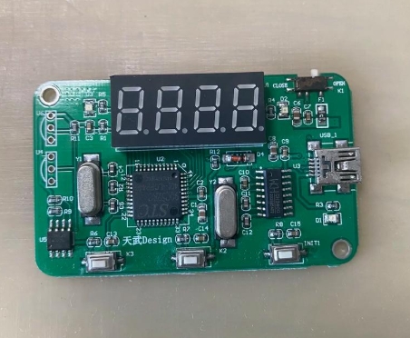
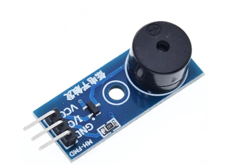
At its core, a GPIO pin can be configured into several key modes: The most basic states are Input and Output. When set as an input, the pin is in a high-impedance state, designed to read the logic level (HIGH or LOW) from an external circuit without drawing significant current. This mode is used for reading switches, buttons, or digital sensor outputs. As an output, the pin actively drives its connected load to either a logic HIGH (typically at the MCU’s supply voltage, Vcc) or a logic LOW (ground potential). This mode controls components like LEDs, relays, or buzzer.
Beyond these basics, GPIOs often feature more advanced internal configurations to handle real-world circuit complexities. A critical configuration is the internal pull-up or pull-down resistor. When a pin is configured as an input and connected to a mechanical switch, the pin can “float” to an undefined voltage when the switch is open, leading to erratic readings. Enabling an internal pull-up resistor weakly connects the pin to Vcc, ensuring a clean HIGH logic level when the switch is open; closing the switch then pulls it definitively to ground (LOW). A pull-down resistor performs the inverse function. Proper management of these pull resistors is essential for debouncing switches and ensuring reliable digital input.
Furthermore, modern MCUs allow GPIOs to be set in other specialized modes. Some pins may be configured as open-drain outputs. In this mode, the pin can only actively pull the line to LOW or go into a high-impedance state; it cannot drive it HIGH. This is crucial for bidirectional communication buses like I2C, where multiple devices share the same line. Understanding these fundamental operational modes—input, output, pull-up/pull-down, and open-drain—is the first pillar of GPIO mastery.
Advanced GPIO Features and Electrical Characteristics
Moving beyond basic software configuration, effective hardware design demands a deep respect for the electrical specifications of GPIO pins. Ignoring these limits is a common source of damaged MCUs and failed projects.
The absolute maximum ratings for voltage and current are non-negotiable constraints. Every GPIO pin has a voltage tolerance, usually relative to its supply rails (Vcc and GND). Applying a voltage outside this range can cause latch-up or permanent damage. Similarly, each pin has a maximum source (output HIGH) and sink (output LOW) current capability, often in the range of 20-50mA for a single pin, with a lower total limit for all pins combined. Directly driving power-hungry devices like motors or multiple high-brightness LEDs from a GPIO pin is a recipe for failure. Instead, drivers such as transistors or MOSFETs must be used as intermediaries to handle the higher load.
Another layer of sophistication comes from alternate function modes. Most MCU pins are multiplexed, meaning a single physical pin can serve multiple internal peripherals. Through register settings, a GPIO can be reconfigured from a simple digital I/O to serve as part of a Serial Peripheral Interface (SPI), Universal Asynchronous Receiver/Transmitter (UART), Pulse-Width Modulation (PWM) generator, or timer input capture channel. For instance, configuring a pin for PWM output allows for precise control of LED brightness or motor speed without CPU overhead. Leveraging these hardware-based alternate functions is key to building efficient and responsive embedded systems, freeing the CPU from bit-banging communication protocols or timing loops.
Speed and timing are also crucial considerations in advanced applications. GPIO pins have finite slew rates and capacitive load driving capabilities, which affect signal integrity at high frequencies. For fast digital communication or precise timing, features like direct memory access (DMA) linked to GPIO can be used to transfer data without CPU intervention. Furthermore, many modern MCUs offer interrupt-on-change capabilities on their GPIOs. Instead of constantly polling an input pin in software—a wasteful process—the developer can configure the pin to generate a hardware interrupt when its logic level changes. This allows the CPU to sleep or attend to other tasks, waking only when necessary to respond to an external event like a button press or sensor trigger, dramatically improving system power efficiency.
Practical Application and Best Practices
Theoretical knowledge culminates in practical application. A standard workflow for using a GPIO involves several disciplined steps that ensure robust operation.
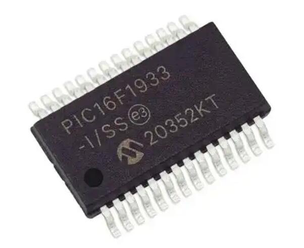
The first step is always consulting the MCU’s datasheet and reference manual. These documents provide the definitive map: pinout diagrams, alternate function mappings, register descriptions for control, and all electrical specifications. Assuming pin functions can lead to frustrating debugging sessions.
Initialization through register configuration follows a clear sequence: First, enable the clock signal to the specific GPIO port (a common power-saving feature on ARM Cortex-M cores). Next, configure the pin’s mode (input/output/alternate function/analog) and output type (push-pull/open-drain). Then, set the output speed if applicable, and finally configure the pull-up/pull-down resistors if needed. Modern development environments and libraries often abstract these steps into convenient functions.
Circuit design around GPIOs requires careful planning. For outputs driving inductive loads like relays or motors, a flyback diode must be used to suppress voltage spikes that could destroy the MCU pin. For inputs connected to long wires or noisy industrial environments, additional external filtering with resistors and capacitors may be necessary to prevent false triggering from electromagnetic interference (EMI).
Software practices are equally important. Implementing debouncing logic for mechanical switches, either in hardware with an RC filter or in software with timers and state machines, is essential for reliable input reading. When using interrupt-driven GPIOs, keep Interrupt Service Routines (ISRs) as short as possible—often just setting a flag—and defer processing to the main loop. For bidirectional communication pins (like open-drain I2C lines), ensure software correctly manages the transition between input and output modes during protocol execution.
Finally, robust systems plan for failure and unexpected states. Implementing watchdog timers that can be triggered by GPIO monitoring, using input validation routines, and designing circuits with protective components like series current-limiting resistors all contribute to creating durable embedded products that perform reliably over time.
Conclusion
MCU GPIO pins represent the essential bridge between the abstract world of software code and tangible physical interaction. Their apparent simplicity belies a depth of functionality that ranges from reading a simple button press to participating in high-speed communication protocols. Mastery of GPIO involves not only understanding software configuration modes—input, output with pull resistors—but also respecting hard electrical limits and leveraging advanced features like alternate functions and hardware interrupts. By adhering to best practices in circuit design and software architecture, developers can transform these versatile pins into reliable channels for control and sensing. As embedded systems continue to proliferate into every aspect of modern life, from IoT nodes to automotive systems, the principles of effective GPIO utilization remain an indispensable skill in every hardware developer’s toolkit. For those sourcing components for their next innovative design, efficient procurement platforms such as ICGOODFIND provide essential support in navigating the complex semiconductor landscape.