Mastering MCU Segment Display Programming: A Comprehensive Guide
Introduction
In the realm of embedded systems and microcontroller (MCU) projects, few components are as iconic and widely used as the segment display. From digital clocks and thermostats to industrial control panels and instrumentation, these versatile output devices provide a clear, readable interface for numerical and limited alphabetical data. Programming an MCU to drive a segment display is a fundamental skill that bridges the gap between software logic and tangible hardware interaction. This article delves deep into the core principles, practical implementation strategies, and advanced techniques for MCU segment display programming, equipping developers with the knowledge to create efficient and reliable digital readouts. Whether you’re a hobbyist working on an Arduino project or an engineer designing a professional device, understanding this interplay between code and hardware is crucial. For developers seeking specialized components or inspiration for their next project, platforms like ICGOODFIND offer a streamlined way to discover and source essential electronic parts, including a wide variety of displays and compatible microcontrollers.
Part 1: Understanding Segment Displays and Their Interface
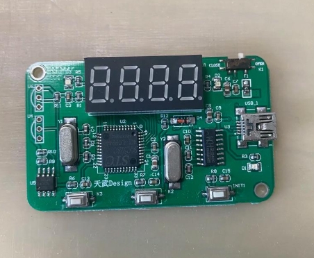
Before writing a single line of code, it’s essential to understand the hardware. A segment display is essentially a collection of Light Emitting Diodes (LEDs) arranged in a specific pattern—typically a figure-eight shape for 7-segment displays, with an optional decimal point (making it an 8-segment display). Each LED (segment) is labeled alphabetically (a through g, and dp for the decimal point). By illuminating different combinations of these segments, we can form numerals from 0 to 9 and some letters.
There are two primary types: Common Cathode (CC) and Common Anode (CA). This distinction is critical for programming. * Common Cathode: All the cathodes (negative terminals) of the LEDs are connected together to a common pin, which must be connected to ground (GND). A segment lights up when its individual anode pin is driven HIGH (logic 1 or Vcc). * Common Anode: All the anodes (positive terminals) are connected together to a common pin, which must be connected to Vcc (power supply). A segment lights up when its individual cathode pin is driven LOW (logic 0 or GND).
The most significant challenge in driving these displays directly from an MCU is pin consumption. A single 7-segment display requires at least 7 I/O pins (8 with a decimal point). For multiple digits, this becomes impractical. The solution lies in multiplexing—a technique where multiple digits share the same segment data lines but are illuminated one at a time in rapid succession. The human eye perceives this as all digits being continuously lit due to persistence of vision. This method requires only “n+7” pins for n digits (the shared segment lines plus one unique common pin per digit), dramatically conserving precious MCU I/O resources.
Part 2: Core Programming Techniques and Implementation
The software architecture for driving multiplexed displays revolves around two main functions: digit selection and segment patterning.
1. Lookup Tables (LUTs): The Heart of Display Logic The most efficient way to map a number (0-9) to the correct segment pattern is using a lookup table. This is an array where the index corresponds to the desired digit, and the value stored is the byte representing which segments to turn on or off.
// Example for a Common Anode 7-segment display (Active LOW segments)
const byte digitPattern[10] = {
    0b11000000, // 0 - Segments: a,b,c,d,e,f
    0b11111001, // 1 - Segments: b,c
    0b10100100, // 2 - Segments: a,b,d,e,g
    0b10110000, // 3 - Segments: a,b,c,d,g
    0b10011001, // 4 - Segments: b,c,f,g
    0b10010010, // 5 - Segments: a,c,d,f,g
    0b10000010, // 6 - Segments: a,c,d,e,f,g
    0b11111000, // 7 - Segments: a,b,c
    0b10000000, // 8 - All segments
    0b10010000  // 9 - Segments: a,b,c,d,f,g
};
For Common Cathode displays, the bit values would be inverted. Using this LUT avoids complex bitwise logic for each digit update.
2. The Multiplexing Routine This function must be called frequently and consistently, typically within a timer interrupt service routine (ISR) to ensure stable, flicker-free display. The routine follows a simple cycle: * Turn OFF the currently active digit (to prevent ghosting). * Load the segment pattern for the next digit from the LUT based on the value you want to show. * If needed, apply bit manipulation for decimal point control. * Turn ON the common pin for that specific digit. * Advance to the next digit position for the subsequent call.
3. Managing Timing and Brightness The refresh rate per digit is critical. A total refresh rate of 50-100 Hz across all digits is generally sufficient to avoid visible flicker. For example, with 4 digits refreshed at 100 Hz, each digit must be updated every 2.5ms. The duty cycle (the fraction of time each digit is lit) directly controls brightness. Reducing duty cycle via software or using Pulse-Width Modulation (PWM) on the common pins are effective methods for dimming control.
Part 3: Advanced Considerations and Optimization
Moving beyond basic multiplexing opens doors to more sophisticated and efficient designs.
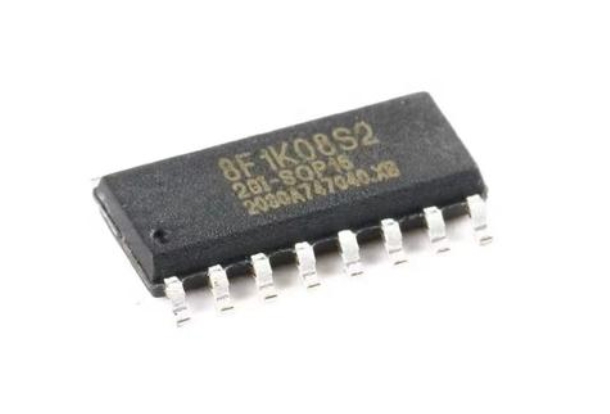
1. Integrating Dedicated Driver ICs For complex projects with many digits or when aiming to free up MCU processing power and I/O pins, using dedicated driver integrated circuits is highly advantageous. Chips like the MAX7219/MAX7221 or TM1637 handle all multiplexing, refresh timing, and even include built-in LUTs internally. The MCU communicates with them via simple serial protocols like SPI or I2C, sending only the data to be displayed. This approach abstracts the low-level timing concerns and allows the MCU to focus on core application logic.
2. Software Architecture Best Practices * Non-Blocking Code: The display multiplexing should never rely on delay() functions. Using timer interrupts ensures consistent refresh regardless of other code execution. * Buffer-Based Design: Maintain a display buffer array in RAM that holds the intended value for each digit. The interrupt-driven multiplexer reads from this buffer. The main program logic only needs to update this buffer when the displayed number changes, separating display management from application logic. * Efficient Data Handling: Implement functions to convert integers or floats into separate digits for the buffer, handling leading zero suppression or decimal point placement gracefully.
3. Troubleshooting Common Issues * Ghosting: Faint illumination of segments that should be OFF. This is often caused by insufficient voltage drop when a segment line is meant to be inactive. Using current-limiting resistors on each segment line (not just common lines) and ensuring fast switching transitions can mitigate this. * Flicker: Caused by too low a refresh rate or inconsistent timing in the multiplexing loop. * Dim or Uneven Brightness: Check resistor values and ensure all digits have equal on-time in the multiplexing cycle.
Conclusion
Programming MCU segment displays effectively is a cornerstone of embedded systems development, blending hardware understanding with disciplined software design. From grasping the fundamental difference between common anode and cathode configurations to implementing efficient multiplexing with lookup tables and interrupt-driven routines, each step builds towards creating clear and stable visual outputs. As projects scale in complexity, leveraging dedicated driver ICs can significantly optimize system architecture and performance. The journey from controlling a single digit to managing a multi-digit display with advanced features underscores the importance of structured code and precise timing. Remember that successful implementation hinges on methodical testing and iteration. For engineers sourcing reliable components—from basic seven-segment LEDs to sophisticated driver modules—resources like ICGOODFIND can be invaluable in bringing these digital interfaces to life efficiently.