8051 MCU Buzzer Program: A Comprehensive Guide to Generating Sound with Embedded Systems
Introduction
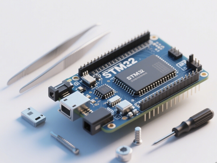
The 8051 microcontroller has remained one of the most popular and enduring embedded systems platforms since its introduction by Intel in 1980. Its simple architecture, low cost, and widespread availability make it an excellent choice for countless applications, including sound generation through buzzers. Buzzer programming represents a fundamental skill in embedded systems development, serving as the foundation for alarms, notifications, user interfaces, and simple audio applications. This comprehensive guide explores the intricacies of 8051 MCU buzzer programming, providing both theoretical understanding and practical implementation techniques. Whether you’re creating a simple alert system or developing more complex audio patterns, mastering buzzer control with the 8051 microcontroller opens up numerous possibilities in embedded design. Throughout this article, we’ll examine the hardware requirements, programming methodologies, and advanced techniques that make the 8051 an ideal platform for sound generation projects.
Understanding Buzzers and Their Integration with 8051 Microcontroller
Types of Buzzers and Their Operating Principles
Buzzers come in two primary varieties: active and passive, each with distinct characteristics and driving requirements. Active buzzers contain an internal oscillation circuit that produces a fixed frequency tone when DC voltage is applied, making them simpler to implement but offering limited control options. These are ideal for basic alert sounds where specific frequency control isn’t necessary. Passive buzzers, conversely, lack an internal oscillator and require an external signal to generate sound, typically a square wave at the desired frequency. This additional complexity provides greater flexibility, allowing developers to create different tones, melodies, and sound patterns by varying the frequency and timing of the driving signal.
The fundamental operating principle behind buzzers involves converting electrical energy into sound waves through mechanical vibration. In electromagnetic buzzers, current through a coil creates a magnetic field that moves a ferromagnetic disk, while piezoelectric buzzers use the piezoelectric effect where certain materials change shape when voltage is applied. Understanding these mechanisms is crucial for effective buzzer implementation, as it influences factors like power requirements, sound volume, and frequency response. The 8051 microcontroller’s GPIO pins typically cannot supply sufficient current to drive buzzers directly, necessitating additional driver circuitry such as transistors or MOSFETs to amplify the control signals.
8051 Microcontroller Architecture Relevant to Buzzer Control
The 8051 microcontroller’s architecture contains several features that make it particularly well-suited for buzzer control applications. Its precise timing capabilities through timers and interrupts form the foundation for generating accurate frequencies essential for proper buzzer operation. The 8051 typically includes two or three 16-bit timers (Timer 0, Timer 1, and sometimes Timer 2) that can be configured in various modes to generate precise delays and square waves. These timers can operate independently of the main program execution, allowing for consistent sound generation while the microcontroller performs other tasks.
Another critical architectural feature is the bit-addressable memory space, which enables efficient control of individual I/O pins without affecting others on the same port. This capability is particularly valuable when the buzzer control pin shares a port with other peripherals or indicators. The 8051’s interrupt system also plays a vital role in complex sound generation, allowing the microcontroller to respond immediately to timer overflows or external events that might require immediate audio feedback. Furthermore, the relatively simple instruction set and predictable instruction timing facilitate creating precisely timed audio sequences without complex calculations or compensation for pipeline inconsistencies found in more advanced architectures.
Hardware Configuration and Circuit Design
Proper hardware configuration is essential for successful buzzer implementation with the 8051 microcontroller. The basic circuit involves connecting the buzzer to a microcontroller GPIO pin through a driver transistor. For passive buzzers, the GPIO pin provides the frequency signal, while for active buzzers, it simply enables or disables the buzzer. A typical configuration uses an NPN bipolar junction transistor (such as the 2N2222) or an N-channel MOSFET as a switch, with appropriate base or gate current limiting resistors to protect both the microcontroller and transistor.
Power considerations are crucial in buzzer circuit design. Buzzers often require more current than the 8051’s GPIO pins can supply (typically limited to 1-2mA per pin), making external driving elements necessary. The circuit should include a flyback diode when using electromagnetic buzzers to suppress voltage spikes caused by the collapsing magnetic field when current is suddenly switched off. For applications requiring variable volume, pulse width modulation (PWM) can be implemented either through software or using the 8051’s hardware timers in PWM mode if available. Proper decoupling capacitors near both the microcontroller and buzzer power connections help maintain stable operation by filtering power supply noise generated by the buzzer’s operation.
Programming Techniques for Buzzer Control
Basic Buzzer Activation and Frequency Generation
The simplest form of buzzer control involves turning an active buzzer on and off using straightforward port manipulation. For an active buzzer connected to pin P1.0, the code might be as simple as setting and clearing the corresponding bit:
#include

sbit buzzer = P1^0; // Buzzer connected to P1.0

void main() {
    while(1) {
        buzzer = 1; // Turn buzzer on
        // Delay for some time
        buzzer = 0; // Turn buzzer off
        // Delay again
    }
}
For passive buzzers, generating specific frequencies requires more precise timing control. The fundamental approach involves toggling the buzzer pin at a rate corresponding to half the period of the desired frequency. For example, to generate a 1kHz tone (period of 1ms, half-period of 0.5ms), the pin must be toggled every 500 microseconds. This can be achieved using precise software delays or more efficiently using timer interrupts:
#include

sbit buzzer = P1^0;
unsigned char toggle_count = 0;

void timer0_isr(void) interrupt 1 {
    TH0 = 0xFC; // Reload values for 1kHz at 11.0592MHz
    TL0 = 0x66;
    buzzer = ~buzzer; // Toggle buzzer pin
}

void main() {
    TMOD = 0x01; // Timer 0 in mode 1
    TH0 = 0xFC; // Initial values for 1kHz
    TL0 = 0x66;
    ET0 = 1; // Enable Timer 0 interrupt
    EA = 1; // Enable global interrupts
    TR0 = 1; // Start Timer 0

    while(1) {
        // Main program loop
    }
}
Advanced Sound Patterns and Melody Implementation
Creating complex sound patterns and melodies requires more sophisticated programming techniques that go beyond simple frequency generation. Pulse Width Modulation (PWM) can be employed to control volume by varying the duty cycle of the driving signal while maintaining frequency consistency. This technique is particularly useful for creating emphasis in audio sequences or implementing dynamic volume control in response to user input or environmental conditions.
For musical applications, generating different notes requires producing specific frequencies corresponding to musical scales. By calculating appropriate timer reload values for each note and implementing a duration control mechanism, developers can program complete melodies:
#include

sbit buzzer = P1^0;

// Frequencies for notes (in Hz)
code unsigned int notes[] = {262, 294, 330, 349, 392, 440, 494, 523};
code unsigned int note_durations[] = {100, 100, 100, 100, 100, 100, 100, 100};

void play_note(unsigned int frequency, unsigned int duration) {
    unsigned long period;
    unsigned int reload_value;
    unsigned int i;

    period = 1000000UL / frequency; // Period in microseconds
    reload_value = 65536 - (period / 2);

    TMOD = 0x01;
    TH0 = reload_value >> 8;
    TL0 = reload_value & 0xFF;
    ET0 = 1;
    EA = 1;
    TR0 = 1;

    for(i = 0; i < duration; i++) {
        delay_ms(10); // Simple delay function (implementation not shown)
    }

    TR0 = 0; // Stop timer
    buzzer = 0; // Ensure buzzer is off
}

void main() {
    unsigned char i;

    for(i = 0; i < 8; i++) {
        play_note(notes[i], note_durations[i]);
        delay_ms(50); // Short pause between notes
    }

    while(1);
}
This approach can be extended with more sophisticated data structures to represent complete songs with varying note durations, rests, and dynamic markings.
Optimizing Code for Efficient Buzzer Control
Efficient code is essential in embedded systems where resources are limited and real-time performance is often critical. Several optimization techniques can significantly improve buzzer program efficiency in 8051 applications. Using lookup tables for frequently accessed values like timer reload values for specific frequencies eliminates runtime calculations and reduces code size and execution time. These tables can be stored in code memory using the ‘code’ keyword to preserve limited internal RAM:
code unsigned int frequency_reload[] = {
    64021, // C4
    64103, // D4
    64185, // E4
    64260, // F4
    64331, // G4
    64400, // A4
    64463, // B4
    64524  // C5
};
Interrupt-driven approaches generally provide more efficient use of processor resources than polling methods. However, careful interrupt management is crucial to maintain responsiveness in systems with multiple interrupts. For complex applications requiring simultaneous buzzer control and other functions, implementing a state machine architecture for sound generation allows non-blocking operation where the main program continues execution while sound sequences play in the background.
Memory optimization is particularly important in the 8051 with its limited internal RAM. Using compact data types (like ‘bit’ flags for simple status indicators), minimizing variable scope, and reusing memory locations where possible all contribute to more efficient memory utilization. Additionally, inline assembly language can be used for timing-critical sections where compiler-generated code may not meet precise timing requirements.
Practical Applications and Troubleshooting
Real-World Implementation Scenarios
The 8051 MCU buzzer program finds applications across numerous domains from simple consumer electronics to sophisticated industrial systems. In household appliances, buzzers provide audible feedback for button presses, cycle completion alerts in washing machines and dishwashers, and warning indicators in microwave ovens and smoke detectors. Automotive applications include turn signal indicators, warning chimes for open doors or unfastened seatbelts, and parking sensors. Industrial implementations encompass machinery operational status indicators, emergency stop warnings, and process completion notifications.
Medical devices represent another significant application area where reliability is paramount. Patient monitors use distinctive tones for different alarm conditions based on priority levels—higher priority alarms typically use louder volumes with more urgent repetition patterns. Infusion pumps employ buzzers to indicate completion of medication delivery or occlusions in the administration set. In these critical applications,robust program design with comprehensive error checking ensures reliable operation even in electrically noisy environments common in medical settings.
Consumer electronics leverage buzzer capabilities for user interface enhancement rather than just warning signals. Mobile phones use vibrato effects (subtle frequency variations) to create more pleasant notification sounds. Gaming devices implement multi-tone sequences for game events and feedback. Even modern IoT devices often include basic buzzers for local notifications when network connectivity is unavailable or as a backup to cloud-based alerts.
Common Challenges and Debugging Strategies
Despite its conceptual simplicity,buzzer implementation often presents challenges that require systematic debugging approaches.A common issue involves insufficient sound volume,frequently resulting from inadequate drive current rather than programming errors.Measuring current draw with a multimeter can identify this problem,solved by ensuring appropriate driver transistor selection with sufficient current gain or adding amplification stages.
Another frequent challenge concerns timing inaccuracies in generated frequencies,caused by incorrect timer reload value calculations or interrupt latency miscalculations.The fundamental relationship between desired frequency(f),timer clock frequency(Fosc),and timer reload value(TRV)follows:TRV=65536-(Fosc/(12×f×2))for standard 8051 timers in mode 1.Debugging timing issues often involves oscilloscope measurements of the output waveform to verify both frequency accuracy and signal integrity.
Electromagnetic interference(EMI)represents another common challenge,both from the buzzer affecting other circuits and external noise affecting microcontroller operation.Power supply decoupling,signal separation,and physical isolation techniques help mitigate these issues.In severe cases,a small resistor in series with the buzzer or ferrite beads may be necessary to suppress high-frequency noise.
Software-related problems often involve unexpected behavior during interrupt-heavy operations or resource conflicts.Meticulous interrupt priority management,efficient ISR design with minimal processing,and comprehensive testing under various operational scenarios help identify and resolve these issues.Structured debugging approaches beginning with simplest cases(single continuous tone)and progressively adding complexity help isolate problem sources effectively.
Future Trends and Advanced Integration
As embedded systems evolve,buzzer technology and control methodologies continue advancing alongside microcontrollers.Piezo-electric buzzers increasingly dominate new designs due to their lower power consumption,wider frequency response,and longer operational lifespans compared to electromagnetic alternatives.Surface-mount technology(SMT)buzzers enable more compact designs while maintaining adequate sound pressure levels for most applications.
Integration with other peripherals represents a significant trend in modern embedded design.The 8051 MCU buzzer program increasingly functions as part of larger systems incorporating additional sensors,inputs,and communication modules.For example,a security system might combine buzzer outputs with motion sensors,temperature monitors,and wireless communication modules.Creating cohesive architectures where these components interact seamlessly requires careful system design prioritizing modularity and clear interfaces between subsystems.
Power efficiency continues driving innovation in both hardware and software approaches.PWM techniques now commonly implement dynamic power adjustment based on application requirements—lower volume during normal operation with temporary increases for critical alerts.Software optimizations focus on minimizing active processing time through advanced sleep modes that briefly awaken only for essential tone generation before returning to low-power states.
For developers seeking comprehensive components and resources for such projects,ICGOODFIND offers an extensive repository of technical documentation,schematic references,and implementation examples that can significantly accelerate development cycles across various applications.The platform’s curated selection ensures quality components compatible with diverse design requirements from prototyping through production.
Conclusion
Mastering 8051 MCU buzzer programming provides embedded systems developers with a versatile tool for creating audible user interfaces,warning systems,and even simple musical applications.This comprehensive guide has explored fundamental concepts ranging from basic buzzer types through advanced programming techniques and practical implementation considerations.The journey begins with understanding hardware fundamentals—recognizing differences between active and passive buzzers,and implementing appropriate driver circuits—then progresses through software techniques from simple port manipulation to sophisticated interrupt-driven frequency generation employing precise timing control.
The real value of these skills emerges when applying them across diverse application scenarios from consumer products through industrial equipment and medical devices.Each domain presents unique requirements influencing implementation decisions regarding sound patterns,frequency selection,and reliability measures.Troubleshooting forms an essential skill complementing programming knowledge,systematically addressing common issues like insufficient volume,timing inaccuracies,and electromagnetic interference through methodical debugging approaches.
As embedded systems continue evolving toward greater integration and efficiency,buzper programming maintains its relevance through adaptation—incorporating power management strategies,surface-mount technologies,and advanced integration with sensor systems and communication modules.Whether implementing simple alerts or complex audible interfaces,the foundational principles covered herein provide a robust framework supporting diverse application requirements across industries and use cases.